How to connect the ignition strobe light

Status
Not open for further replies.

telect

Newbie
Joined
Oct 11, 2021
Messages
2
Helped
0
Reputation
0
Reaction score
0
Trophy points
1
Visit site
Activity points
15
I had a very simple chinese strobe light to set ignition timing but accidentaly it got wrapped around the engine fan
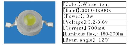
All the wires were pulled out and the led got broken.
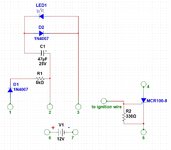
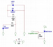
I've changed the led, but have no clue to what pins should i connect the wires. There are 3 pins and 4 wires. Two of them goes to the thyristor and the other two goes to the battery.
Tried to simulate the wiring in the Multisim, but got no luck. Seems like Multisim is unable to simulate even the simpliest schematic where the thyristor is involved, coz I've always got an error.
Can you please help me to wire it correctly
 

Attachments

  • schematics.jpg
    183.1 KB · Views: 204
  • schematics.jpg
    183.1 KB · Views: 210

"3 pins and 4 wires"? It looks to me like what you've drawn is 7 pins.

If I had to guess, I'd say connect pin 4 to pin 2, pin 5 to pin 7, pin 6 to pin 3. I think pin 1 should also go to pin 6.

I'm not familiar with multisim, but have you tried simulating this with another tool (LTSPICE, TINA, etc.)?
 
Thank you Barry for help.
Finally found some time to finish it.
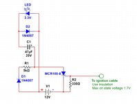
Here is the working scheme. Maybe someone will need it, since the cost of it is less than a $10.
It is better to take case with a lens from a flashlight.
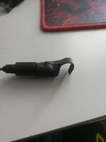
Solder a piece of wire or a thin metal plate to the gate of the thyristor. Wrap it all with insulation and then hang it on the spark plug wire.
You can take the LED from the flashlight also
 

Attachments

  • Scheme eng.jpg
    206.3 KB · Views: 156
  • A940DbxJkAU.jpg
    903.2 KB · Views: 162
  • led.jpg
    103.9 KB · Views: 162

Status
Not open for further replies.
Cookies are required to use this site. You must accept them to continue using the site. Learn more…