Continue to Site

Welcome to EDAboard.com

Welcome to our site! EDAboard.com is an international Electronics Discussion Forum focused on EDA software, circuits, schematics, books, theory, papers, asic, pld, 8051, DSP, Network, RF, Analog Design, PCB, Service Manuals... and a whole lot more! To participate you need to register. Registration is free. Click here to register now.

How to connect hall effect sensors and PICto measure the solar PV energy??

Status
Not open for further replies.

swethamenon

Member level 4
Member level 4
Joined
Sep 12, 2012
Messages
70
Helped
0
Reputation
0
Reaction score
0
Trophy points
1,286
Activity points
1,745
Im doing project on solar energy m/m.how to connect sensors and PIC to it..
can any1 show the block diagram for that.
current sensor in series and voltage sensor in parellel to the PV output.
is the output from them connect directl to the PIC ports??
Where should connect the load(dc battery)/.?
 

Im doing project on solar energy m/m.how to connect sensors and PIC to it..
can any1 show the block diagram for that.
current sensor in series and voltage sensor in parellel to the PV output.
is the output from them connect directl to the PIC ports??
Where should connect the load(dc battery)/.?

Hi Swethamenon
A short answer :
It depends on how much is out put voltage of your hall effect sensor instead of maximum current . if it is high , you've to attenuate it . ( i don't think it is high ! ) hence you can directly connect it to your MCU ( it's ADC ) or perhaps using a buffer , or amplifier before connecting it to your MCU .
Best Wishes
Goldsmith
 

You can see this nice projects :

LCD Solarcontroller 20A / 200A Version
https://www.icplan.de/seite19.htm

MiniLogger V3.0
**broken link removed**

MiniLogger V1.0
**broken link removed**


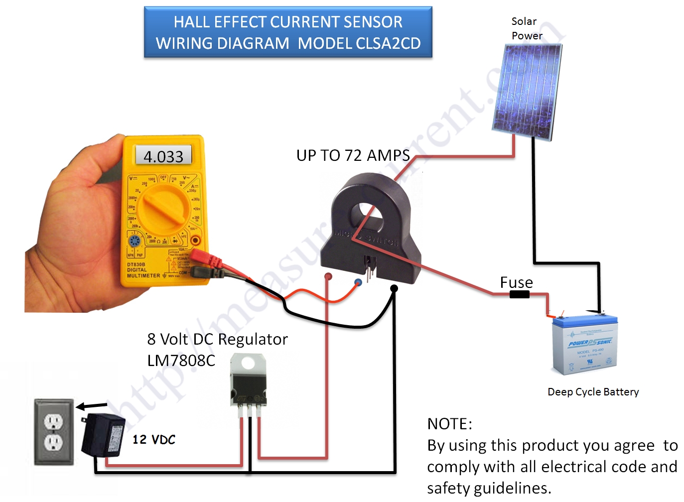
clsa2cd-measure-current.jpg

**broken link removed**


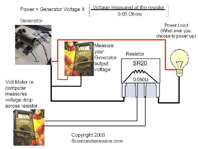
bg-cur2.jpg

https://scienceshareware.com/bg-current-monitoring.htm


To read values on PIC µC use PIC ADC and this tutorials to learn :

PIC-based Digital Voltmeter (DVM)
https://embedded-lab.com/blog/?p=396


PIC16F688 Digital Voltmeter
https://www.electronics-lab.com/projects/test/016/index.html


This is enough for start.... ;-)
 
Last edited:
  • Like
Reactions: FvM

    FvM

    Points: 2
    Helpful Answer Positive Rating
Hi Swethamenon
A short answer :
It depends on how much is out put voltage of your hall effect sensor instead of maximum current . if it is high , you've to attenuate it . ( i don't think it is high ! ) hence you can directly connect it to your MCU ( it's ADC ) or perhaps using a buffer , or amplifier before connecting it to your MCU .
Best Wishes
Goldsmith

Thank you...
how the energy measure..
i mean have to connect load right?where to connect
how would be th connection?
cann u simply show the dgm..with panel,sensors,pic and load.
or no nned to connect load?
 

Thank you...
how the energy measure..
i mean have to connect load right?where to connect
how would be th connection?
cann u simply show the dgm..with panel,sensors,pic and load.
or no nned to connect load?
What do you mean by connecting the load ? i hope you know that , when you don't have any load , you won't have any current . you want measure current through the load . isn't it ?
If you want show value of your current or do something else , with that , you can connect out put voltage of your hall effect sensor to your MCU . but if you just want measure it , i think tpetar's post will be incredible !

Best Wishes
Goldsmith
 

Thank you...
how the energy measure..
i mean have to connect load right?where to connect
how would be th connection?
cann u simply show the dgm..with panel,sensors,pic and load.
or no nned to connect load?

In the diagram above (post #3), the black object on top of which is written "UP TO 72 AMPS" is the hall effect sensor.
The panel is labelled as "SOLAR POWER".
The output of the hall effect sensor (which in the diagram in post #3 is connected to the voltmeter) will go to the PIC.
The battery is the load.

If you want to measure current and/or energy, there obviously needs to be a load. Otherwise what current and/or energy will you be measuring? And why? The whole point is to measure current through the load.

You just need to identify or define the load. In the diagram in post #3 (and any solar charge controller), the main load is the battery.

Hope this helps.
Tahmid.
 

What do you mean by connecting the load ? i hope you know that , when you don't have any load , you won't have any current . you want measure current through the load . isn't it ?
If you want show value of your current or do something else , with that , you can connect out put voltage of your hall effect sensor to your MCU . but if you just want measure it , i think tpetar's post will be incredible !

Best Wishes
Goldsmith

We will connect panel to the load..in this path current sensor in series and volt sensor in parllel..then wer'll connect PIC??
im askg that whthr want to knw the max cuurent value of the load..and then discnt it and feed the o/ps of sensors to pIC ports??

How to take the time for the measurement of energy??
Sun's intensity vary with time..so in what time duration has to consider?
That time is to be chosen from the timer in the PIC(changing the prescalar) right??
 

Don't know if this applies...

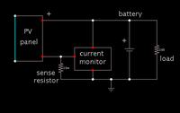
This diagram shows how I hooked up a charge current monitor to my PV panels and batteries.


The sense resistor is referenced to ground, so the op amp detects a small volt level above ground.

The current monitor draws power from the positive supply.
 

We will connect panel to the load..in this path current sensor in series and volt sensor in parllel..then wer'll connect PIC??
im askg that whthr want to knw the max cuurent value of the load..and then discnt it and feed the o/ps of sensors to pIC ports??

What current sensor are you using or plan to use?
The reading from the sensor should be taken while battery is being charged. So, the outputs of the sensors are always connected to the PIC.

How to take the time for the measurement of energy??
You can take readings of voltage, current and time.

Sun's intensity vary with time..so in what time duration has to consider?
Depends on the location of the installation. It could be between 2 and 6 hours.

That time is to be chosen from the timer in the PIC(changing the prescalar) right??
The time-keeping has to be dealt with by you in the software. The prescaler only affects the time for a single timer-increment.

Hope this helps.
Tahmid.
 

What current sensor are you using or plan to use?
The reading from the sensor should be taken while battery is being charged. So, the outputs of the sensors are always connected to the PIC.


You can take readings of voltage, current and time.


Depends on the location of the installation. It could be between 2 and 6 hours.


The time-keeping has to be dealt with by you in the software. The prescaler only affects the time for a single timer-increment.

Hope this helps.
Tahmid.[/QUOT
Thank you..I f i want to measure energy of 1hr time drtn..how i enter this?How much energy values can be stored?
if i want to retain 1 weeks V,I,Energy value will it b possible
 

What current sensor are you using or plan to use?
The reading from the sensor should be taken while battery is being charged. So, the outputs of the sensors are always connected to the PIC.


You can take readings of voltage, current and time.


Depends on the location of the installation. It could be between 2 and 6 hours.


The time-keeping has to be dealt with by you in the software. The prescaler only affects the time for a single timer-increment.

Hope this helps.
Tahmid.

Im using 2panel series which is parllel with 2 series panel.this similar structure is again parllel with this..so 8 panels r using
Voltage of 1 panel is abt 15v and I is 3v.so total is 30V and 12A.
How to design the value of input resistor of sensor LV20 NP??

How much voltage value can PIC withstand??
Is it 5v and less than that?
 

What current sensor are you using or plan to use?
The reading from the sensor should be taken while battery is being charged. So, the outputs of the sensors are always connected to the PIC.


You can take readings of voltage, current and time.


Depends on the location of the installation. It could be between 2 and 6 hours.


The time-keeping has to be dealt with by you in the software. The prescaler only affects the time for a single timer-increment.

Hope this helps.
Tahmid.

How much time cycle it takes to mul V&I.?depend on that T for enrgy is choosen right?
T is THE SAMPLING PERIOD NA?How it is found??
 

@swethamenon

For all your questions you can see answers in post #3.


But i want to measure energy.for that time is taken from PIC itself..ie after sensing 1 V&I value..the sampling period is taken as T.
The time cycle required to mul bothe n move to some regesiter..how much time cycle it is required for that??
How the time cycle from that is known.
I jst went through the datasheet but i dint gt it


You have answer and example in post #3.
 

Perhaps we can help you better if you explain what you have understood so far, and what confuses you.
 

How to design the value of input resistor of sensor LV20 NP??

How much voltage value can PIC withstand??
Is it 5v and less than that?

If you are talking about installing a resistance inline...

It should be as small ohms as possible, yet provide a usable reading.

Example:
Suppose you want to generate a reading of 1 V when 12 A is going through the resistor. Then you will use a .083 ohm value. But then it will dissipate 12 W of power, wasted as heat. That is something to think twice about.

Suppose you want to generate 1/10 V.
That will require a resistance of .008 ohm. It will dissipate 1.2 watts of power (wasted as heat). This seems less wasteful. You can make a low ohm resistance from a suitable length of wire. Say, several inches of 18 gauge copper.

There is the question whether your pic can detect volt levels under .1 V, and create proportional values accordingly.
 

Perhaps we can help you better if you explain what you have understood so far, and what confuses you.

Energy=V*I*t
V&I are sensed from the sensor and give to the PIC port
How to select the time is my confusion..
What is time cycle..i know it is the time taken to process one instruction in the program, right??

I think the time cycles to mul V&I (sampling and conversion too) multiplied by the sampling period(if 2Mhz using then 0.5microsec) can use as the t.
What is ur opinion?
How to select 't'?
 

Status
Not open for further replies.

Part and Inventory Search

Welcome to EDABoard.com

Sponsor

Back
Top