Continue to Site

Welcome to EDAboard.com

Welcome to our site! EDAboard.com is an international Electronics Discussion Forum focused on EDA software, circuits, schematics, books, theory, papers, asic, pld, 8051, DSP, Network, RF, Analog Design, PCB, Service Manuals... and a whole lot more! To participate you need to register. Registration is free. Click here to register now.

How to calculate the threshold values for the Schmitt trigger based interface for VR

Status
Not open for further replies.

venkatgandham

Junior Member level 2
Joined
Aug 31, 2011
Messages
21
Helped
0
Reputation
0
Reaction score
0
Trophy points
1,281
Activity points
1,497
I am designing a Variable reluctance sensor interface, I am taking a help from the attached circuit to design the Interface.

I have calculated the threshold values for the VR sensor interface based on the conditions I have mentioned in the attached document.

Va and Vb are the filtered signals coming from the VR sensor.

I have the following questions related to the attached circuit.

1) What is the role of R3 resistor in the positive feedback loop?

2) There is a Vbias applied to the V+ terminal of the Schmitt trigger.

3) I have calculated the V+ and V- threshold values for the Schmitt trigger and I wanted to confirm if the procedure I followed is right.

4) I took 1.4 V diodes for protecting the circuit. Does that make sense?

I appreciate your help in understanding the design.

https://obrazki.elektroda.pl/7373201200_1371359530.jpg
https://obrazki.elektroda.pl/6541857200_1371359532.jpg

For Html,


http://obrazki.elektroda.pl/7373201...oda.pl/7373201200_1371359530_thumb.jpg[/img]
 
Last edited:

1) What is the role of R3 resistor in the positive feedback loop?

R3 is unnecessary if you are using an op amp.

However if you are using a comparator, then R3 is needed as a pullup resistor.

4) I took 1.4 V diodes for protecting the circuit. Does that make sense?

Not sure where you would find silicon diodes with a forward voltage of 1.4 V, but ordinary red led's will give you 1.7 or 1.8 V (useful in case they turn out to be cheaper).
 

    V

    Points: 2
    Helpful Answer Positive Rating
Hello BradtheRad,

Thank you for the reply, sorry I only drew one diode, but I plan on using two diodes, which will make it 1.4 V. I am using the Schmitt trigger comparator for the interface design. It's better to use comparators than opamps for converting the analog signal into a digital signal, because opamps are sloppy when used as a comparator because they get saturated when over driven which may cause it to recover slowly. However opamps can be effective when used for low frequency inputs. I will try the interface with opamps too and analyze the output of the circuit performance. Why do we need a pull up resistor when the VDD (+5v) is applied to the supply pin of the comparator? Is it because of the positive feedback due to which some of the output is fed back and the output decreases?
 

Why do we need a pull up resistor when the VDD (+5v) is applied to the supply pin of the comparator? Is it because of the positive feedback due to which some of the output is fed back and the output decreases?

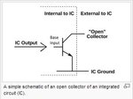
On the basis of outputs, comparators can also be classified as open drain or push–pull.
  • Comparators with an open-drain output stage use an external pull up resistor to a positive supply that defines the logic high level.
  • In open collector outputs,when the inverting input is at a higher voltage than the non inverting input, the output of the comparator connects to the negative power supply. When the non inverting input is higher than the inverting input, the output is 'floating' (has a very high impedance to ground).
Inputs Output (without connecting a pullup resistor)
− > + Grounded
+ > − Floating

  • With a pull-up resistor and a 0 to +5 V power supply, the output takes on the voltages 0 or +5 and can interface with TTL logic:
  • Push pull output does not need a pull up resistor and can also source current unlike an open drain output.
  • Only moderate speed comparators can have open collector/open drain without detoriating performance. All really fast comparators & also some newer "micropower" comparators use push pull outputs.

So,it depends on comparator you are using.If you are using an open collector output one like LM 339 you need a pull up resistor.If you use a push pull output one like TLC3702 then you do't need to use a push-pull resistor.

The TLC3702 is functionally similar to the LM339 but uses one-twentieth of the power for similar response times. The push-pull CMOS output stage drives loads directly without a power-consuming pullup resistor to achieve the stated response time

  • Yes,op-amps are not designed to be used as comparators. A comparator is designed to be used with large differential input voltages, whereas op amps normally operate with their differential input voltage minimized by negative feedback.
  • Comparators are designed for clean fast switching and, as a result, often have worse dc parameters than many op amps.
  • But it may be convenient to use an op amp as a comparator in applications requiring low VOS, low IB, and wide CMR. It is never worthwhile to use an op amp as a comparator if high speed is important
 

Attachments

  • Care.JPG
    Care.JPG
    17.6 KB · Views: 98
Last edited:
Yes,op-amps are not designed to be used as comparators. A comparator is designed to be used with large differential input voltages, whereas op amps normally operate with their differential input voltage minimized by negative feedback.
Yes, generally. But almost meaningless for the present problem:
- variable reluctance sensor signals are slow by nature (e.g. maximum kHz frequency)
- most general purpose OPs don't have any problems with differential input voltages up to the supply rails

Output slew-rate of OPs is the most serious limitation in similar applications. If you can accept it, there's nothing against using an OP as comparator.

P.S.: If the circuit output is intended to drive logic ICs, the minimum input slew rate specifications of the respective logic family should be considered however. It might conflict with low OP slew-rates, unless the signal is processed by another ST function.
 
Last edited:
Output slew-rate of OPs is the most serious limitation in similar applications. If you can accept it, there's nothing against using an OP as comparator.
When i've written that op amps are not designed for use as comparators,i was trying to explain that they may saturate if over-driven which may cause it to recover comparatively slowly.
 
Status
Not open for further replies.

Part and Inventory Search

Welcome to EDABoard.com

Sponsor

Back
Top