Continue to Site

Welcome to EDAboard.com

Welcome to our site! EDAboard.com is an international Electronics Discussion Forum focused on EDA software, circuits, schematics, books, theory, papers, asic, pld, 8051, DSP, Network, RF, Analog Design, PCB, Service Manuals... and a whole lot more! To participate you need to register. Registration is free. Click here to register now.

How to calculate the resistor and capacitor values for a bridge diode full-wave rectifier?

Okasian

Newbie
Newbie level 1
Joined
Dec 3, 2024
Messages
1
Helped
0
Reputation
0
Reaction score
0
Trophy points
1
Visit site
Activity points
10
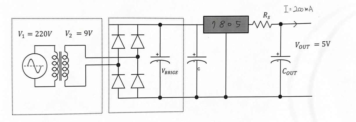
wi2mTS4Y.jpg***


Hello. I need to design the circuit so that the output power is 1W, but I'm not sure what values to use for Rs and Cout. Could you explain how to calculate them?
 
..

and: if you use an 7805 (or any other electronics device) --> read it´s datasheet.
It tells you how to operate it. This is reliable information.

Don´t rely on random internet sources. Most of them contain mistakes, are incomplete...

Rely on
* informations from manufacturers
* universities
* schools
* reputable electronics designers

The manufacturer internet page of the device schold be the first place to visit. For newbies as well as for professionals.
There you find the datasheet and additional helpful informations like application notes, design notes, simulation tools..
This is all you need (indeed more than you need) ...
.. only for special applications you may need additional detail informations. (like when you want to use the voltage regulator as a constant current source. So not used the usual way)

****
To the circuit:
It uses a transformer with 9V output. On no load a small 9V transformer may easily output 12V RMS sine.
The rectified bridge voltage thus may go up to (12V x sqrt(2)) - (2x 0.6V) = 17V - 1.2V = about 16V (first part is the peak of a sine. Second part is the drop of two diodes)

If the output voltage is 5V ... then 11V need to be wasted. This (11V x current) is the (peak) power that has to be dissipated as heat.
On a 0.2A load .. I guess realistically you may expect up to 1.8W of heat (average). --> The 7805 wil get hot. Too hot without heat sink. Thus add a heatsink.

Due to loss (heat) and rather heavy transformer .. nowadays one uses switch mode supplies.
Many devices come with with 5V DC plug supplies. Usually there is always such a power supply laying around. (Maybe from a broken device)

There are rare reasons to nowadays use the "mature design" power supply.
Can you tell us the reason why you have chosen it?

Klaus
 
Additionally, if your design requirement is to produce 1W rather than 5V you need both constant voltage and constant current (5V * 0.2A = 1W) and that is impossible with that circuit.

You can LIMIT the output to 1W by adding a resistor between the two capacitors at the input of the 7805 but the output voltage will drop as soon as its minimum input voltage limit is reached. It wouldn't be considered a reliable solution.

Brian.
 
As stated, specifications in post #1 are inconsistent. Can you sketch expected Vout versus Iout characteristic to clarify your requirements?
--- Updated ---

There are a few linear regulators with programmable current limit on the market, e.g. LT3081 that allows to implement constant current/constant voltage source with a single IC.
 
Last edited:

LaTeX Commands Quick-Menu:

Part and Inventory Search

Welcome to EDABoard.com

Sponsor

Back
Top