Continue to Site

Welcome to EDAboard.com

Welcome to our site! EDAboard.com is an international Electronics Discussion Forum focused on EDA software, circuits, schematics, books, theory, papers, asic, pld, 8051, DSP, Network, RF, Analog Design, PCB, Service Manuals... and a whole lot more! To participate you need to register. Registration is free. Click here to register now.

How to calculate MMIC MLIN Length and Width using ADS

pusparaga

Full Member level 4
Full Member level 4
Joined
Oct 19, 2013
Messages
197
Helped
4
Reputation
8
Reaction score
4
Trophy points
1,298
Activity points
2,988
I am designing MMIC Power Amplifier. I want to calculate Lamda/4 line MLIN Length and Width at 26 GHz while designing MMIC PA. In MIC design, we can easily calculate MLIN Length and Breadth once we know parameters like Dielectric Constant, Dielectric Height, Frequency, Z0, Electrical Length, Tangential Loss etc.
In MMIC PDK kit where are these informations like Dielctric Constant, Dielectric Height, Eletrical Length and Tangetial Loss? How to calculate MLIN Length and Width Microsrtip Line Calculator
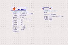
 

Attachments

  • MMIC_MLIN.jpg
    MMIC_MLIN.jpg
    56.8 KB · Views: 121
You'll hardly have lambda/4 elements in 26 GHz MMIC. Nevertheless traces should be treated as TL for accurate modeling.
The ADS document you have linked in a previous thread is discussing the procedure in detail. Data have to be obtained from your PDK.


IC tapes are using dedicated formats, e.g. GDSII rather than PCB artwork formats Gerber or odb++.
 
If you don't know the stackup / process specification, one possibility is to analyze some length of line using the model that you showed, and look at S21 phase in simulation results. You can then tweak line width for low S11 using a long line (>360 degree S21 phase). And after finding that 50 Ohm line width, you can tweak line length to have 90 degree S21 phase.
 
If you don't know the stackup / process specification, one possibility is to analyze some length of line using the model that you showed, and look at S21 phase in simulation results. You can then tweak line width for low S11 using a long line (>360 degree S21 phase). And after finding that 50 Ohm line width, you can tweak line length to have 90 degree S21 phase.
Sorry, I have a question that has nothing to do with the current question but it is on MMIC design though. I am new to MMIC, mostly been doing hybrid designs, I have the s2p info for an active device but will that be enough to perform a design like for a simple amplifier?( I mean can I implement, the ideal transmission lines for the design since it will not be in actual lengths(mm/um) ?) .
Or I would need a full MMIC process info to do that?
If yes, ADS has some packages for MMIC (GAs and GaN I think), so can I use the pdk along side the active device s2p file I have? Thanks

The active device is the TGF2120 from Qorvo.
 

LaTeX Commands Quick-Menu:

Part and Inventory Search

Welcome to EDABoard.com

Sponsor

Back
Top