Continue to Site

Welcome to EDAboard.com

Welcome to our site! EDAboard.com is an international Electronics Discussion Forum focused on EDA software, circuits, schematics, books, theory, papers, asic, pld, 8051, DSP, Network, RF, Analog Design, PCB, Service Manuals... and a whole lot more! To participate you need to register. Registration is free. Click here to register now.

how to average, stabilize signal

Status
Not open for further replies.

NortonTriumph

Newbie level 3
Newbie level 3
Joined
Jan 16, 2009
Messages
3
Helped
0
Reputation
0
Reaction score
0
Trophy points
1,281
Activity points
1,332
stabilize signal

Hello,
I have a circuit that switches a solenoid. My models all incorporated a stable 1.8vdc input signal. The true signal is taken from a blinking diode circuit and it goes 0-1V.
I believe this confuses the Op-Amp 741 and it cannot handle this. Can someone shoot me in the right direction of tools to stabilize this signal. I am aware capacitors, resistors, filters are possibilities but don't know the approach. I may look for a stable signal source but it may be hard to find.
Thanks
 

how to stabilize a signal

I'm not sure what you mean by the amp can't handle a 0-1 V input?

What do you mean by stabilize? What is unstable, and what do you mean by unstable.

What sort of circuit are you implementing with the amp and solenoid? Can you attach a sketch, or describe it? Are you using it as a comparator?

Also, don't use a 741 they are effectively antiques. There are thousands of better amps availible for the same price or less.
 

how to average an analogue signal

Hello,
The circuit to activate a remote solenoid works, so I didn't include all the other components. When a voltage is recieved from a transmitter, it is amplified and some other power supplies are relayed to magnetize and fire the solenoid. For design I used a signal supply of a AA batt (≈ 1.5v). This was fine and amplification, transistors, and relays all work good enough. My power supply is +/- 18v.
This is not meant to be a precision finely tuned device. I'm more of a rock crusher than a diamond cutter. I think this is within my capability, and have proceeded quite far. I'm operating near/at saturation on my op amp, and don't care, yet. It just needs to recieve a signal and put voltage on the path toward a solenoid. Fire once, releasing a pin to trip a trap.
This is accomplished with 12volt relays and possibly a transistor switched to ground. Ive played with both designs and they work but I haven't decided the final design probably will be dictated by current. I figured I better tackle my signal manipulations at this time.
I realized my signal would be different than my design battery. In fact I had to pull the real signal from a cordless phone (reciever) and can get a pulsed (unstable) 0-1volt signal on my multimeter. I was hoping that it would be good enough to process and fire the circuit once. I believe this non-linear signal is too jumpy for the op amp to process. I don't know really, because I haven't done design before as you can tell. I believe the process of smoothing a signal is common, though this is not really noise but on/off type signal. This is the unstability I was referring to. It is by design, of the phone manufacturer, but not a desireable characteristic of a recieved signal.
I am using the op-amp as a amplifier, considered comparator, Don't know which is better in this application, just wanted to get my signal larger. initially it was 5omV.
I've written enough for now, I hope it is sufficient,
Thanks for you thoughts/time
Paul

Added after 3 hours 3 minutes:


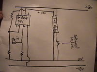
I have tried to supply a conceptual sketch. The solenoid is a 24V but works okay at 18v. I was considering using a capacitor to energize the magnet. Possibly two relays inline that switch the capacitor from charge to ground through the valve when a signal is recieved. I may also use a transistor as a switch to ground. Recall, I just need to pull a small load to trip a trap from a transmitted signal.
I had to struggle through my learning curve with what I know, this may not be the way to do it, but as far as I know currently. I believe I can now understand responses.
Thanks Paul
Oh! forgot, I think I need a transistor after the Op-Amp to increas current. I have tested this and believe the op-amp output can switch power to the relay through the transistor. As you can see, I'm feeling around as I learn
 

Right, I think I see what you're trying to do. Your 'signal' is a digital line which either turns a relay on or off. You are trying to condition the signal (possibly 0-1 V), to drive a relay?
And the conditioning you have just now, is using a lm741 in a non-inverting configuration (unless your schematic is wrong, but that's not a comparator.) to amplify the digital on/off signal.

What you really want to do is get yourself a comparator, or get a decent op-amp, and connect it as a comparator with hysteresis (the data sheet of any comparator will show you how to do this). Also, I've not worked with relay's for a while, but as I remember it you should really be driving this with a transistor (biPolar) and not an op-amp, since it is a current and not a voltage which switches the relay (I think). Anyway, you could implement a working circuit without the extra comparator IC, by adding hysteresis to the circuit which drives the relay.
 

Yes, that's the goal. Drive a solenoid from a signal.
Honestly, I don't know if it is a digital or analog signal that I'm pulling. The sigal is transmitted from a cordless phone base to the handset. Usually, people cut the speaker wires and work with that. I didn't get that option and just probed the handset till I found a voltage only present when the base was transmitting. I looked in the vicinty of a blinking LED and found a point to solder an output wire, its very hard to say if it is part of the same circuit, but it is a site that is only active during the "find handset" transmittance.Could I be seeing an analog signal with voltage fluctuations resulting from the diode blinking, consuming power? I'm aware DMM convert digital signals into voltages but not sure how a meter displays this. I see voltages all through a range of -0.5 to 1.2 volts. They appear on the DMM screen between blinking/sampling period.
Thanks for the help, I shall investigate hysteresis and DAC conversions, and improved Op-amplifiers. It is true, I work with much antiquated equipment, it seems its not so much the task but knowing the available tools in this world.
I still use contact breakers on my motorcyles!
and just sold my '77 ford
Talk soon
Paul
 

You want a digital signal to drive your relay. Thus you want to condition it to be a logic 1 or 0. You want to use a comparator to acheve this, an open collector one would allow you to shift the voltage level to the desired value and set the output current controlling the relay. To this comparator you want to add hysteresis, which will stop multiple switching at the cross-over point. I don't know if this is the cause of your instability, as you've not really explained the problem you're trying to overcome.
The first thing to do is to use a comparator with hysteresis, since the circuit you sketched is not suitable for the application you are using.
If there is switching occuring some time after the initial switch, then it is probably the signal you're comparing has dropped below the level it's being compared to. In this case you need to use some additional logic to create a single pulse at a specific event - using a monostable and/or flip-flops.
 

In your original post you say you want to drive the relay from the status from a 'blinking diode' (LED??). What is the rate of the blink? Every second? Every minute? ...

Maybe you can consider using a MOSFet to drive the valve instead of a relay? And for sure don't forget frewheel diodes on the valve and the relay coil.
 

Status
Not open for further replies.

Part and Inventory Search

Welcome to EDABoard.com

Sponsor

Back
Top