How simple measure current on 300kHz?
- Thread starter asrock70
- Start date
- Status
- Not open for further replies.
WimRFP
Advanced Member level 5

- Joined
- Apr 16, 2010
- Messages
- 1,589
- Helped
- 594
- Reputation
- 1,176
- Reaction score
- 538
- Trophy points
- 1,393
- Location
- Netherlands
- Activity points
- 15,026
How much voltage drop can you accept across your current meter?
galvanic isolation required?
sinusoidal or square wave?
what will be the readout device (ADC, just volt or current meter, etc)?
accuracy?
galvanic isolation required?
sinusoidal or square wave?
what will be the readout device (ADC, just volt or current meter, etc)?
accuracy?
asrock70
Full Member level 4

Sinusoidal, no galvanic isolation , readout device, Agilent 34401.
What is it
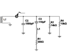
Picture shows a simplified equivalent circuit.
C3 + L1 form a series resonant circuit
C2 is parasitic and L2 is tune inductor.
The goal is
Xc2=XL2 and frequencies is resonant frequencies of L1+C3.
At that moment, current will be approximate maximum.
I'm looking for a simple way to be able to track the progress of current when tuning frequency and L2

schmitt trigger
Advanced Member level 5

What is the purpose of R2 and R4?
I understand R1 is the inductor's equivalent series resistance...which by the way, at that frequency will be different from the DC resistance.
I understand R1 is the inductor's equivalent series resistance...which by the way, at that frequency will be different from the DC resistance.
WimRFP
Advanced Member level 5

- Joined
- Apr 16, 2010
- Messages
- 1,589
- Helped
- 594
- Reputation
- 1,176
- Reaction score
- 538
- Trophy points
- 1,393
- Location
- Netherlands
- Activity points
- 15,026
Very likely the frequency range of the DVM doesn't go to 300 kHz.
I would go for a (shielded) current probe and an oscilloscope. If you don't have an oscilloscope you could use a current probe with a two diode (voltage doubling) rectifier, but that requires serious design as you have low current level.
You can make a current probe yourself from a high permeability ferrite with sufficient secondary windings that go to a 50 Ohms input of an oscilloscope. Of course you can also load the current transformer with a resistor and use a high impedance probe. You can't make the current ratio too small, otherwise your signal may dissapear in the noise.
Don't take for granted expensive looking current probes. When the impedance level at the measurement position is relatively high, the current probe may respond to voltage also. That is why I prefer shielded current probes (own construction) for probing high impedance circuits. If you have access to the return (ground) wire, you may put the current probe around the return wire reducing respons due to voltage.
WimRFP
Advanced Member level 5
- Joined
- Apr 16, 2010
- Messages
- 1,589
- Helped
- 594
- Reputation
- 1,176
- Reaction score
- 538
- Trophy points
- 1,393
- Location
- Netherlands
- Activity points
- 15,026
@Carpenter: Is this true for all measurement ranges (included mV range)? I had some meters in the past that didn't measure correctly at the lowest voltage range (and it was mentioned in the manual).
@asrock70: If you add a series resistor somewhere in the circuit, be aware of differential to common mode conversion issues. You may meausure something that is actualy not across the current sensing resistor.
@asrock70: If you add a series resistor somewhere in the circuit, be aware of differential to common mode conversion issues. You may meausure something that is actualy not across the current sensing resistor.
carpenter
Full Member level 6
Accuracy Specifications for 34401A (6.5 digit) say True RMS AC voltage for 100mV range and frequency 100kHz-300kHz have error 4%+0.5% (% of reading + % of range).
- Status
- Not open for further replies.
Similar threads
-
How measure differential uV signals on larger bias/offset voltage?
- Started by userx2
- Replies: 6
-
-
Spice simulation - How to check Max Voltage and max Current
- Started by jumbodas
- Replies: 2
-
-
