Prince Charming
Member level 2

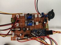
Hello, this is my sad post. I've designed a motion sensor alarm and soldered it part by part, it is mostly burned now including the Arduino. I want to know why is it a terrible idea to switch Boost converters with low side MOSFETs.

My most terrific mistake was to connect the boost converter directly to power without trying it separately, thus it gave 30V output, I immediately turned the switch off but it kept on 30V until I plugged the USB cable off the Arduino. The Arduino was connected to pc from a different source but I didn't think it had anything to do with it. After some time 555 timer got hot as expected as its maximum voltage rating is 18V. Interestingly Arduino's voltage regulator is also damaged because it gets really hot from now on even when it is just connected to PC. Even though the boost converters are connected parallel they divided the 9V adapter input to each other as 4.5, I didn't understand why, maybe current? I think Voltage x Current is similar in input and output of converters, considering the Al2 and D1 wasn't connected at the test, there was no power abusive device, it was only the timer IC, I don't think boost converter's failure to raise the voltage is caused by low current limit. The 24V boost converter can't sustain 24V at output but it can only raise to 4 volts (lower than input) on the contrary the 12V boost converter was successful.
Okay so many unknowns are here, the thing I am asking is, what terrible design do you see in this such simple circuit. Is the high voltage at converters finding an alternative way to ground through Arduino when IRLZ44 is off? Can current flow backwards from boost converters? Is it better to do P side switching instead of N here? Should I use P MOSFET with optocouplers?
There are usually shutdown pins in converters but this was a module with inductor and capacitor, I want to learn how to shut them down as well.
I know the post is mixed up but I hoped the mistakes are obvious, thanks.
plus: raw pin was missing on the model so I drew VCC and Raw the same, in real life ofc that's not the case also batteries wasn't connected at the test.

Last edited by a moderator:

