preoccupied
Newbie level 3

Recently i have been doing a project of wideband CP microstrip antenna. It `s simply for general purpose, with no more requirement than a good circular polarization and relative large bandwidth. Before setting to the work, I referred to the book <broadband microstrip antennas>. several basic geometries are shown there, from which I picked the circular patch with a slit on the top(I will then upload the structure I use).
My confusions are:
1. Is AR bandwidth the most important factor that can dictate circular polarization? At first, I didn`t put much effort in this. All I am focused on are smith chart and S11. although smith chart and S11 plot show good and satisfactory results to me, the tags array test turn out to be problemetic.
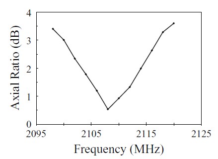
here is the AR bandwidth that I got after realizing its importance. though, it`s not perfectly matching my thought.
mine:

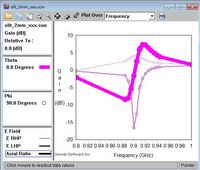
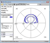
also uploaded is my version of radiation pattern, what information can you read out, I wonder

a better view from textbook should be like this:

2. how much information can smith chart tell us? It`s easy to get an idea of matching condition, vswr bandwidth, or even a rough picture of CP? now let`s just look at CP if I didn`t misunderstand. below is quoted from one book:
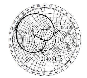
"Another way to recognize whether the given dimensions are optimum for the best AR is to look at the impedance plot of the antenna. If there is a kink (extremely small loop) in the impedance plot corresponding to the excitation of the two orthogonal modes, it will yield the best AR at the kink frequency. Instead of a kink, a small loop or the absence of the loop in the impedance plot yields poor AR." Accordingly, I have this screenshot posted

Do I mix up concepts of CP and wideband, or Smith Chart is definitely telling about CP as I thought?
3. when the dielectric and the thickness are fixed, what can we do to improve the vswr bandwidth? some books say "The BW of the antenna is limited by its AR and not by its VSWR." Is this true?
4. one last thing to make sure, is the feed location affecting CP? or it`s just the geometry that makes a difference?
Thank you for your time viewing and considering my questions. If I happen to ask some silly questions, please feel free to tell me and correct them.
- - - Updated - - -
besides, what does gain in dBi tell us? I know by definition it`s gain relative to isotropic. But what`s the significance?
My confusions are:
1. Is AR bandwidth the most important factor that can dictate circular polarization? At first, I didn`t put much effort in this. All I am focused on are smith chart and S11. although smith chart and S11 plot show good and satisfactory results to me, the tags array test turn out to be problemetic.
here is the AR bandwidth that I got after realizing its importance. though, it`s not perfectly matching my thought.
mine:

also uploaded is my version of radiation pattern, what information can you read out, I wonder

a better view from textbook should be like this:

2. how much information can smith chart tell us? It`s easy to get an idea of matching condition, vswr bandwidth, or even a rough picture of CP? now let`s just look at CP if I didn`t misunderstand. below is quoted from one book:
"Another way to recognize whether the given dimensions are optimum for the best AR is to look at the impedance plot of the antenna. If there is a kink (extremely small loop) in the impedance plot corresponding to the excitation of the two orthogonal modes, it will yield the best AR at the kink frequency. Instead of a kink, a small loop or the absence of the loop in the impedance plot yields poor AR." Accordingly, I have this screenshot posted

Do I mix up concepts of CP and wideband, or Smith Chart is definitely telling about CP as I thought?
3. when the dielectric and the thickness are fixed, what can we do to improve the vswr bandwidth? some books say "The BW of the antenna is limited by its AR and not by its VSWR." Is this true?
4. one last thing to make sure, is the feed location affecting CP? or it`s just the geometry that makes a difference?
Thank you for your time viewing and considering my questions. If I happen to ask some silly questions, please feel free to tell me and correct them.
- - - Updated - - -
besides, what does gain in dBi tell us? I know by definition it`s gain relative to isotropic. But what`s the significance?
Last edited:
