chiques
Full Member level 3

- Joined
- Nov 21, 2007
- Messages
- 170
- Helped
- 2
- Reputation
- 4
- Reaction score
- 2
- Trophy points
- 1,298
- Location
- California
- Activity points
- 2,556


So when my circuit is resonating, there is a 50 Ohm (R) component which centers it in the Smith Chart?
It is, by definition, impossible to deliver real power to a perfectly imaginary load. But in reality, your resonant circuit has a real impedance to it, and that must be known to design a matching network.
Not sure if I'm understanding your problem... are you trying to deliver power to a resonant element/network, or are you trying to use a LC network to impedance match to a resistive load (meaning you want the power delivered to the resistive load, not the LC parts)?So in "the real world", all the resistivity in my transmission lines and my elements some how add up to be 50 Ohm at the resonance?
So in "the real world", all the resistivity in my transmission lines and my elements some how add up to be 50 Ohm at the resonance?
Not sure if I'm understanding your problem... are you trying to deliver power to a resonant element/network, or are you trying to use a LC network to impedance match to a resistive load (meaning you want the power delivered to the resistive load, not the LC parts)?
You keep saying "resonant" but in general when you have an LC network its resonant frequency isn't always relevant when it's used as an impedance transformer. Often the impedance match occurs at a frequency which is close, but not equal to, the resonant frequency.
Impedance matching allows you to obtain maximum power transfer.
The ratio L:C determines LC impedance.
Small L, large C, operates on high current. In this sense it has low impedance.
Large L, small C, needs little current. It has high impedance.
Now suppose you wish to combine the LC with an incoming (or outgoing) resistance. You will choose the L:C ratio accordingly.
where the real impedance comes from which matches to the 50 ohm transmission line
Simplified explanation is that series LC tank has 0 Ohms impedance at it's resonance frequency. But two capacitors C1...C3 forms a step down impedance transformer from 50 Ohms to 22.8 Ohm. What purpose can your circuit have?
The impedance is reactive. It's due to the C opposing voltage changes, and the L opposing Ampere changes.
Furthermore when you put L and C together, it brings in all kinds of interesting effects, including resonant action.
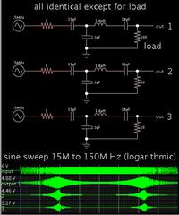
Don't know why, but I seem to be easily entertained by watching animated simulations. This one shows 3 LC tanks having the same resonant frequency. Their ratio of L:C is different. Everything else is identical.
None of the LC tanks has ohmic resistance.
Notice the second LC tank appears to be carrying the most peak watts (4W).
Doing raw math...
The first LC tank has an internal impedance of 3 ohms (at the resonant frequency).
The second, 1 ohm.
The third, 1/3 ohm.
This does not necessarily tell us how to choose an LC combination to match a 50 ohm input resistance.
It does give us a hint of the great variety of simulations that we could learn from, by trying different configurations... by adding various ohm values in the loop, or putting LC in series, or measuring current through components, etc.
...The impedance is reactive. It's due to the C opposing voltage changes, and the L opposing Ampere changes.
We use cookies and similar technologies for the following purposes:
Do you accept cookies and these technologies?
We use cookies and similar technologies for the following purposes:
Do you accept cookies and these technologies?
