Continue to Site

Welcome to EDAboard.com

Welcome to our site! EDAboard.com is an international Electronics Discussion Forum focused on EDA software, circuits, schematics, books, theory, papers, asic, pld, 8051, DSP, Network, RF, Analog Design, PCB, Service Manuals... and a whole lot more! To participate you need to register. Registration is free. Click here to register now.

How can we design a simple circuit to tune the slew rate o an ideal square waveform

Status
Not open for further replies.

bhl777

Full Member level 6
Full Member level 6
Joined
Sep 30, 2008
Messages
363
Helped
0
Reputation
0
Reaction score
0
Trophy points
1,296
Activity points
5,140
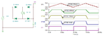
Hi All, I have a general question about the slew rate control of the periodic square waveform. If we have the ideal square waveform whose slew rate is inifite, how can we use some logi circuits and RC components to tune the slew rate of this signal? Thank you! slew rate.png
 

What's the frequency range of the waveform?

If you want a linear rise and fall time, then you need to use some type of integrator on the square-wave.
 
Last edited:

What's the frequency range of the waveform?

If you want a linear rise and fall time, then you need to use some type of integrator on the square-wave.

Hi crutschow, the range is around 1kHz to 50kHz. Would you teach me how to use the integrator? Thank you!
 

Put in a series capacitor which gives a spikey waveform.
Add resistors in different positions relative to the capacitor (in series with it, in parallel with it, other end to ground or supply+, etc.).
Play with values until you see your leading edge become more square. Expect amplitude to drop a little.
 

Now I realize I misunderstood when I posted how to restore the edge so it rises more quickly. You want to create a ramp appearance. Then the capacitor should be installed between the signal and ground, to create the integrator as recommended in post #2.
 

One way is to use a programmable current source to vary the slew rates as shown below. A lot will depend on required frequency, level, etc.
 

Attachments

  • slew.png
    slew.png
    17.7 KB · Views: 129
  • Like
Reactions: bhl777

    bhl777

    Points: 2
    Helpful Answer Positive Rating
Here's the LTspice simulation of a slew rate control circuit using two complementary current mirrors to generate a constant charge and discharge current into a capacitor (C1).
This generates a linear ramp for the rise and fall of the pulse.
Pots U1 and U2 control the rise and fall times respectively.

Slew Rate.PNG
 
  • Like
Reactions: bhl777

    bhl777

    Points: 2
    Helpful Answer Positive Rating
Status
Not open for further replies.

Part and Inventory Search

Welcome to EDABoard.com

Sponsor

Back
Top