Continue to Site

Welcome to EDAboard.com

Welcome to our site! EDAboard.com is an international Electronics Discussion Forum focused on EDA software, circuits, schematics, books, theory, papers, asic, pld, 8051, DSP, Network, RF, Analog Design, PCB, Service Manuals... and a whole lot more! To participate you need to register. Registration is free. Click here to register now.

How can I connect a SIM5360E module to my PC?

detavot

Newbie
Joined
Jul 3, 2024
Messages
5
Helped
0
Reputation
0
Reaction score
0
Trophy points
1
Activity points
31
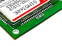
Hello everyone. I have a module for SIM5360E but it is not mounted on any board. I want to establish a connection between my module and my PC so that I can practice AT commands (there is no other option). I thought of using an external USB-to-Serial converter like CP2102 but it does not work. I looked up the pins of this module, would it be fine to just design a USB-to-Serial converter on the module itself and use that? I have no idea.

Thank you for your time nad help.
 
The CP2102 should work. Please recheck your connections.
--- Updated ---

You can also try the FTDI module instead.
 
The CP2102 should work. Please recheck your connections.
--- Updated ---

You can also try the FTDI module instead.
I have attached the Tx, Rx, ground and the 5V pin of the module to the CP2102 (ofc with Tx to Rx and Rx to Tx). This is how it always ends up:
 

Attachments

  • resim_2024-07-03_165508982.png
    resim_2024-07-03_165508982.png
    10.2 KB · Views: 7
I thought of using an external USB-to-Serial converter like CP2102 but it does not work.
"It does not work" gives us not the tinyest information.

***
It seems you want to use UART interface:
then:
* voltage levels need to meet
* timing / baud rate needs to meet
* protocol / sent data needs to meet.

That´s it.

Voltage and timing is given in the datasheets. Every designer needs to read them. Nothing special.
Protocol is what data you send/receive with your PC.

Klaus
Yes, you are correct. Voltage needs are approx. 3.4-4.4V, baud rate according to the datasheet is 115200 bps but I have seen in forums it can work between 9600-115200 so I have been trying all of them out, and the protocol/sent data is indeed met. I think the problem may be with the voltage so I am going to try to do some precise work with a voltage supplier today.
 
Hi,

this is not what I meant. I did not mean to "try" .. I did mean to "know".
you gave one voltage range ... (and I don`t think this given range is correct)
but you need to match 8 ranges:

Modem <--> PC:
------------------
V_OL --> V_IL
V_OH --> V_OH
V_IL <-- V_OL
V_IH <-- V_OH

baud_rate = baud_rate

protocol <--> protocol

Klaus
 
Which module do you have?
1720111435081.png

  • TXD/RXD are 3.3v TTL level which can be directly connected with 3.3v MCU
or
1720111471795.png


Autobauding is default.

1: Make sure your SIM card is unlocked.

2: The product is provided as is without an insulating enclosure. Please observe ESD precautions specially in dry (low humidity) weather.

3: The factory default setting for the GPRS Shield UART is autobaoding.

It supports baud rate from 1200 bps to 115200bps. (Can be changed using AT commands).


Is your data inverted?

Vin connected to external 5~9VDC power supply
or 4.3V> Vbat >3.4
standardized RS–232 interface is used for the communication, and default values for the interface settings as following:
115200bps, 8 bit data, no parity, 1 bit stop, no data stream control
1720110483984.png

1720110593748.png

1720110733616.png

--- Updated ---

Yes, you are correct. Voltage needs are approx. 3.4-4.4V, baud rate according to the datasheet is 115200 bps but I have seen in forums it can work between 9600-115200 so I have been trying all of them out, and the protocol/sent data is indeed met. I think the problem may be with the voltage so I am going to try to do some precise work with a voltage supplier today.
The logic interface is 0<>1.8V but Vbat is 3.4><4.4
 

Attachments

  • 1720111401953.png
    1720111401953.png
    254.9 KB · Views: 3
Last edited:
Which module do you have?
View attachment 192064

  • TXD/RXD are 3.3v TTL level which can be directly connected with 3.3v MCU
or View attachment 192065

Autobauding is default.

1: Make sure your SIM card is unlocked.

2: The product is provided as is without an insulating enclosure. Please observe ESD precautions specially in dry (low humidity) weather.

3: The factory default setting for the GPRS Shield UART is autobaoding.

It supports baud rate from 1200 bps to 115200bps. (Can be changed using AT commands).


Is your data inverted?

Vin connected to external 5~9VDC power supply
or 4.3V> Vbat >3.4
standardized RS–232 interface is used for the communication, and default values for the interface settings as following:
115200bps, 8 bit data, no parity, 1 bit stop, no data stream control
View attachment 192059
View attachment 192060
View attachment 192061
--- Updated ---


The logic interface is 0<>1.8V but Vbat is 3.4><4.4
Unfortunately, I do not have a board. Just the module itself. I was given the task of figuring out how to connect the module to the PC when I didn't have any board to go off of. Thank you for your resources and kindness, I will keep your knowledge in mind
 
Hi,

this is not what I meant. I did not mean to "try" .. I did mean to "know".
you gave one voltage range ... (and I don`t think this given range is correct)
but you need to match 8 ranges:

Modem <--> PC:
------------------
V_OL --> V_IL
V_OH --> V_OH
V_IL <-- V_OL
V_IH <-- V_OH

baud_rate = baud_rate

protocol <--> protocol

Klaus
Ah! Thank you kindly, I did not realise about half of these parameters. The voltage range I gave was for VBAT, though for the logic interface I'd need 0-1.8V. Sorry for the inconvenience, I am very new to this.
--- Updated ---

Unfortunately, I do not have a board. Just the module itself. I was given the task of figuring out how to connect the module to the PC when I didn't have any board to go off of. Thank you for your resources and kindness, I will keep your knowledge in mind
and the module is sim5360e
 
Last edited:

LaTeX Commands Quick-Menu:

Similar threads

Part and Inventory Search

Welcome to EDABoard.com

Sponsor

Back
Top