Continue to Site

Welcome to EDAboard.com

Welcome to our site! EDAboard.com is an international Electronics Discussion Forum focused on EDA software, circuits, schematics, books, theory, papers, asic, pld, 8051, DSP, Network, RF, Analog Design, PCB, Service Manuals... and a whole lot more! To participate you need to register. Registration is free. Click here to register now.

[SOLVED] How can a lower supply voltage affect circuit performance?

Status
Not open for further replies.

d123

Advanced Member level 5
Joined
Jun 7, 2015
Messages
2,505
Helped
494
Reputation
992
Reaction score
525
Trophy points
1,393
Location
Spain
Activity points
27,148
Hi,

I'd like to lump several questions into one thread if possible, please.

How might changing a circuit from a 12V supply to a 3V supply affect circuit performance, if at all? Can a lower supply be detrimental to comparator response regarding chatter that wasn't present on the 12V version?
On 12V and on 3V circuits, components are correctly selected.

Why would a 12.6V, 0.5 Ohm supply droop with a 1.6 A load? Nothing on the circuit is drawing the other 22.4 that should be available, BJT draws 10mA or 20mA to drive pass devices.

Why would the UVLO comparator chatter and only work correctly with the unwanted 220nF capacitor at the input?
I tried raising UVLO ref from ~254mV to 1V to extend resolution margins, dynamic hysteresis with varied capacitor values to replace Rfb (1.8M one), removed hysteresis, added OA buffer to lower input signal's source impedance, and in the end had to change input signal from lingering a few ms at 3V. Is LM193 too fast for this circuit: with its nominal ~1.3us rise and fall time with 5mV overdrive? Is a ~250mV ref not workable for some reason?

This circuit is being a headache only due to UVLO chatter at both rise and fall without the capacitor at the input to the OA buffer. I don't want an unreliable comparator circuit with slow-changing input signals. Any suggestions and/or observations, please?
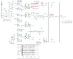
PV AND DC SECTION VC1.JPG

UVLO is ~3V (254mV ref), OVLO is ~12.3V (1.00Vref).

- - - Updated - - -

...also lowered Rpull-up to 2.2k to speed up response but didn't help with PV UVLO chatter around 3V level.
 

Hi,

response regarding chatter that wasn't present
Chatter is a problem of (positive) feedback, not of supply voltage.

I remember when some 10 years ago I had to design digital circuits for the first time with 3.3V supply instead of 5.0V.
I was afraid of functional problems. None of my fears went true.
But still I struggle with some incompatibilities that only change slowly. Like the HD44780 displays, many are still 5V, slow with an interface I still don't like.

- - - Updated - - -

..

Why would a 12.6V, 0.5 Ohm supply droop with a 1.6 A load? Nothing on the circuit is drawing the other 22.4 that should be available, BJT draws 10mA or 20mA to drive pass devices.
What does this mean?
I never heard about a "0.5 Ohm" supply.

Why would the UVLO comparator chatter and only work correctly with the unwanted 220nF capacitor at the input?
I tried raising UVLO ref from ~254mV to 1V to extend resolution margins, dynamic hysteresis with varied capacitor values to replace Rfb (1.8M one), removed hysteresis, added OA buffer to lower input signal's source impedance, and in the end had to change input signal from lingering a few ms at 3V. Is LM193 too fast for this circuit: with its nominal ~1.3us rise and fall time with 5mV overdrive? Is a ~250mV ref not workable for some reason?
Chattering is the symptom, and maybe the increased speed makes things worse, but the main cause - in my opinion - is a wrong design. Not only the schematic ... I assume it's a PCB layout problem.

Klaus

- - - Updated - - -

Hi,

I just noticed you did not speed limit the "Power GoodPV switch". This also could be a root cause.
Try a capacitor from collector to base.

Klaus
 
  • Like
Reactions: d123

    d123

    Points: 2
    Helpful Answer Positive Rating
Hi Klaus,

Thanks.

This circuit is one section of a larger battery charger circuit, I'm still in the theory and design stage as I only have a few hours of electricity a day and sometimes none when the weather is bad which is making life very difficult, depressing and horrendously slow... In the last six weeks I've only been able to do about one working week's effective work.

Great to know that working with lower voltages is the same as higher voltages

Simulator sources have internal resistance parameter. I think <10Hz change of input voltage rate is more a resistance than an impedance almost, at that speed, to put it that way.

"wrong design" - is there something wrong with the circuit? I know you'll see what might go over my head due to inexperience. I think I understand how using non-inverting comparators can cause unwelcome issues due to low input impedance of IN+ input pin = "...a factor which may be critical to a design."

I'll try the collector-base capacitor solution the next time there is enough electricity to turn on the computer, thanks.
 

Hi,

is there something wrong with the circuit?
I did no go very deep into the circuit.
I see nothing really "wrong". I see a lot of effort...many Opamps, comparators and logic.
It's clean, with decoupling capacitors, with hysteresis and - one the first sight - well chosen parts.

But if I had to to the same I'd do it differently. This does not mean that yours is wrong...just another way.
I'd keep the analog part minimal, just to get best quality, then feed it to the ADC of a microcontroller and let the software do all the hysteresis, timing, combinatorial logic.
Less part count, less drift, better to adjust, better to debug....I think it makes life easier.

Do you have a scope? Measure the voltage at C17 during enabling the load.
I see C17 = 1uF is the input reservoir .... but then you try to charge about 800uF....
This may cause trouble.

Compare it with two boxes of water. One is the 10l input box.....if it has a certain level you try to fill a 8000l box to the same level as the 10l box. On first piece of time all drops down to a 0.12% level ...

Now do it the other way round. Have a 8000l input reservoir, when it has a certain level fill the 10l box ...now the level at the input box just drops to 99.88% of level...almost no drop...

I assume you have a reason why you designed it the way you did. From the circuit I assume you want the capacitors close to your load .. to have low ripple = high quality supply at the load..
If so ... I 'd find out the behavior of the load...current draw, peaks, timing, frequency, is there a softstart option...

Klaus
 
  • Like
Reactions: d123

    d123

    Points: 2
    Helpful Answer Positive Rating
Hi Klaus,

Thanks. ...If I could program MCUs, etc, but I haven't got that far yet. I think I still have a lot to learn about analog/hardware and passive components, and I like analog (+ digital/logic solutions) an awful lot. If I had 1/10th of your or other members' learning and experience, the circuit would be similar/identical to your approach. I'm still learning about reducing resistor-induced divider or reference error due to resistor currents and input bias currents, etc...

I see this project as a practical, real-world application and a wonderful learning tool that has a purpose and teaches me a lot of useful things. As I get further with the design stage, I am developing a greater admiration for gate drive wave shaping and timing, battery charger and e.g. Coulumb counter designers and so on. Nothing is easy and even my basic attempt shows me how hard professional applications are to do correctly... My aim is something longer-lasting than what is sold in penny stores and more "honest" than using voltage as SoC indicator.

I have a little, cheap 'scope and DMM but again, I' m only at the conceptual/design stage of studying what is needed when and where necessary, composing the various sub-circuits and simulating ideas to foresee issues and confirm functionality, then slowly fitting them together in simulations to assess viability of concept, but sadly there's not enough electricity to prototype or even breadboard little things where I live at present. :( My short-term realistic? aim is to complete a theoretical version and by then, hopefully have access to a "normal" electricity supply to check real-world functionality, I hope.

And, dohhhh, the 1uF input bypass was an oversight I hadn't contemplated as I was mystified and stuck with the chatter issue. Nice explanation about boxes of water.

Many thanks.
 
Last edited:

Status
Not open for further replies.

Similar threads

Part and Inventory Search

Welcome to EDABoard.com

Sponsor

Back
Top