Pablo_UDEC
Newbie level 5

Hello everyone, I am currently designing a septum horn in a dual-polarization rectangular waveguide. I would like to resolve some questions that have come up, and I would appreciate any recommendations and advice.
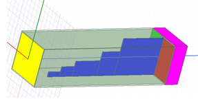
First of all, I have derived the septum calculation from documentation. One of the requirements is that it has a 200 MHz bandwidth. I have read several documents on how to implement them, but I don’t understand how to find the impedances for each step, for example Z_{n+1}. If anyone has information on this that could clarify it, I would appreciate it, because it is important that the septum is designed with a specific bandwidth of interest. As I mentioned earlier, I used a known calculator for those who have designed this type of OMTs, but it does not specify for which BW in particular it is made. I understand that the mathematical theory is of a stepped impedance transformer, and this can be designed with objective parameters such as wide bandwidth and low reflection coefficient. I am attaching the link to the calculator: https://docs.google.com/spreadsheet...WUUmURkmXs/edit?gid=1682293646#gid=1682293646.
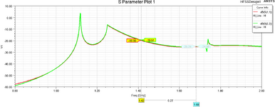
What I did in my HFSS project is a waveguide analyzed for 3 ports. The output port has Ex and Ey with a 90-degree phase shift (I don’t understand how to view this), and both input ports are set to 1W, with one of them having a 180° phase shift. From what I’ve read in different sources, this should happen. Now, I’m not sure if this occurs in the two frequency bands of interest (1.42 and 1.667 GHz). Currently, I have two input ports, but later I will add coaxials to extract both right and left circular polarizations at quarter wavelengths from a short circuit, so I’m not sure if it’s correct that I placed these ports at the end of my OMT. I would like to know if I am extracting values that should be important for the analysis of this instrument. What do you recommend I change, modify, or what other data are important, for example, the modes? Thanks in advance.
First of all, I have derived the septum calculation from documentation. One of the requirements is that it has a 200 MHz bandwidth. I have read several documents on how to implement them, but I don’t understand how to find the impedances for each step, for example Z_{n+1}. If anyone has information on this that could clarify it, I would appreciate it, because it is important that the septum is designed with a specific bandwidth of interest. As I mentioned earlier, I used a known calculator for those who have designed this type of OMTs, but it does not specify for which BW in particular it is made. I understand that the mathematical theory is of a stepped impedance transformer, and this can be designed with objective parameters such as wide bandwidth and low reflection coefficient. I am attaching the link to the calculator: https://docs.google.com/spreadsheet...WUUmURkmXs/edit?gid=1682293646#gid=1682293646.
What I did in my HFSS project is a waveguide analyzed for 3 ports. The output port has Ex and Ey with a 90-degree phase shift (I don’t understand how to view this), and both input ports are set to 1W, with one of them having a 180° phase shift. From what I’ve read in different sources, this should happen. Now, I’m not sure if this occurs in the two frequency bands of interest (1.42 and 1.667 GHz). Currently, I have two input ports, but later I will add coaxials to extract both right and left circular polarizations at quarter wavelengths from a short circuit, so I’m not sure if it’s correct that I placed these ports at the end of my OMT. I would like to know if I am extracting values that should be important for the analysis of this instrument. What do you recommend I change, modify, or what other data are important, for example, the modes? Thanks in advance.
[Moderator action]
Embeeded to Edaboard relevant file hosted to external server
Attachments
Last edited by a moderator:

