Continue to Site

Welcome to EDAboard.com

Welcome to our site! EDAboard.com is an international Electronics Discussion Forum focused on EDA software, circuits, schematics, books, theory, papers, asic, pld, 8051, DSP, Network, RF, Analog Design, PCB, Service Manuals... and a whole lot more! To participate you need to register. Registration is free. Click here to register now.

Honeywell I2C RH Sensor SDA line experiencing fluctuation between Vdd and Vdd/2

Status
Not open for further replies.

shishiker

Junior Member level 1
Joined
Jul 21, 2004
Messages
17
Helped
0
Reputation
0
Reaction score
0
Trophy points
1,281
Activity points
170
Hello,

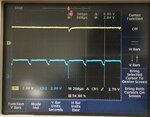
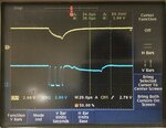
I had a problem when implementing I2C communication between NXP Kinetis K50 micro-controller and Honeywell Humidlcon I2C RH sensor. The RH sensor doesn't acknowledge when receiving the default address 0x27. After testing SCL and SDA signals with oscilloscope, I realized the sensor failed to acknowledgebecause the SDA line fluctuated between around VDD and VDD/2. In my program, the RH sensor receives a measurement command and a read command alternately for every 100ms. In general the signal rises to VDD after the write-bit (logic LOW) following the 7-bit address, whereas drops to about VDD/2 after the read-bit (logic HIGH) following the 7-bit address. Waveform of the SDA line fluctuation (with larger time scale), and detailed I2C SCL and impaired SDA signals are attached.


My pull-up resistors are 2.2K as suggested by the datasheet, current drawn by the RH sensor is below 1mA during I2C communication. This same I2C interface ever worked well with Sensirion SHT35 sensor. After we switched to Honeywell RH sensor, I did minor modification to the code, because Honeywell RH sensors perform measurement and return data without command, but controlled by the last bit of the first byte received from the master. The application circuit of the sensor can be find at
https://sensing.honeywell.com/index.php?ci_id=147072

and the communication document can be found at
https://sensing.honeywell.com/i2c-comms-humidicon-tn-009061-2-en-final-07jun12.pdf


Really couldn't figure out how to fix the problem, please help!
 

Attachments

  • SDA_fluctuate.jpg
    SDA_fluctuate.jpg
    314.8 KB · Views: 164
  • Write_a.jpg
    Write_a.jpg
    365.3 KB · Views: 162
  • Write_b.jpg
    Write_b.jpg
    377.2 KB · Views: 161
  • Read_a.jpg
    Read_a.jpg
    282.1 KB · Views: 149
  • Read_b.jpg
    Read_b.jpg
    330.9 KB · Views: 146

Hi,

Intermediate voltage levels are maybe caused by floating signals. But if there is a 2k2 then floating is impossible.
Please check correct schematic and correct soldering.

If the 2k2 connection is OK, then there may be short circuit condition, when one device switches to LOW, while another device drives HIGH. Driving HIGH is not allowed with SDA thus it should be a coding error.

Klaus
 

Hi Klaus,

The cause is open-drain is disabled, but the same setting ever worked with the previous sensor, it did not occur to me that the code could be wrong.

Best regards,

Yinni
 

Hi,

open-drain is disabled
Why disabled? It should be open drain.

the same setting ever worked with the previous sensor
I don't know whether your code is wrong. But if it's wrong you have to change it.

Wrong code may work with one sensor, but may not work with another sensor.
Wrong code may work with now, but may not work tomorrow.
Wrong code may work with one temperature, but may not work with another temperature.

Klaus
 

Hi Klaus,

Disabling open-drain was a mistake! Like you said wrong code may work today, but may not work tomorrow


Now I have a new problem with the SHT35 RH sensor after I2C pin changed into open-drain.

Since the I2C communication between Honeywell Humidlcon and the microcontroller has been solved, I would like to check if the open-drain setting works with SHT35 or not. Previously (with the above setting) when the failure occurred, it's only the RH sensor doesn't acknowledge, but now when open-drain is enabled I got fluctuation on the SDA line again and the fluctuation frequency (about 0.34ms) is not related to my data updating frequency.
The waveform is attached.

I also tried to internally pull-up the the pins and disable open-drain, again RH sensor no acknowledge


IMG_1101.jpgIMG_1102.jpg
 

Hi,

It's time to show your code. Complete code.

Klaua
 

Hi,

It's time to show your code. Complete code.

Klaua

In the headfile which defines constant, I2C parameters are set:

Code:
#define RH_PIT_USEC_COUNT 200000U //200ms between two commands
#define RH_BAUD 900000U //SCL frequency 900kHz
#define RH_TRANSFER_LENGTH 2
#define RH_RECEIVE_LENGTH 6
#define RH_REQ_CMD 0x24//measurement request
#define RH_ADDRESS 0b01000100//0x44
#define RH_STOP_FLAG_MASK kI2C_TransferDefaultFlag
#define T_REQ_CMD 0
#define RH_MEASURE (uint8_t)0U
#define TEMP_MEASURE (uint8_t)1U

define RH_PIT_USEC_COUNT 200000U //200ms between two commands
Code:
#define RH_BAUD 900000U //SCL frequency 900kHz
define RH_PIT_USEC_COUNT 200000U //200ms between two commands
Code:
#define RH_BAUD 900000U //SCL frequency 900kHz
#define RH_TRANSFER_LENGTH 2
#define RH_RECEIVE_LENGTH 6
#define RH_REQ_CMD 0x24//measurement request
#define RH_ADDRESS 0b01000100//0x44
#define RH_STOP_FLAG_MASK kI2C_TransferDefaultFlag
#define T_REQ_CMD 0
#define RH_MEASURE (uint8_t)0U
#define TEMP_MEASURE (uint8_t)1U
In the setup file, pin configuration is done as follows:

Code:
/*Set up I2C Clock Signal Pin for RH and Temp*/
#ifdef C_I2C1_SCL_RH_CLK
	port_pin_config_t tempHumidClkPortConfig;

	tempHumidClkPortConfig.mux = C_I2C1_SCL_RH_CLK_MUX;
	tempHumidClkPortConfig.pullSelect = kPORT_PullDisable;
	tempHumidClkPortConfig.slewRate = kPORT_FastSlewRate;
	tempHumidClkPortConfig.passiveFilterEnable = kPORT_PassiveFilterDisable;
	tempHumidClkPortConfig.openDrainEnable = kPORT_OpenDrainEnable;
	tempHumidClkPortConfig.lockRegister = kPORT_UnlockRegister;

	PORT_SetPinConfig(PORTC, 10, &tempHumidClkPortConfig);
	PORT_SetPinInterruptConfig(PORTC, 10, kPORT_InterruptOrDMADisabled);
#endif

	/*Set up I2C Data Signal Pin for RH and Temp*/
#ifdef C_I2C1_SDA_RH_DAT
	port_pin_config_t tempHumidDatPortConfig;

	tempHumidDatPortConfig.mux = C_I2C1_SDA_RH_DAT_MUX;
	tempHumidDatPortConfig.pullSelect = kPORT_PullDisable;
	tempHumidDatPortConfig.slewRate = kPORT_FastSlewRate;
	tempHumidDatPortConfig.passiveFilterEnable = kPORT_PassiveFilterDisable;
	tempHumidDatPortConfig.openDrainEnable = kPORT_OpenDrainEnable;
	tempHumidDatPortConfig.lockRegister = kPORT_UnlockRegister;

	PORT_SetPinConfig(PORTC, 11, &tempHumidDatPortConfig);
	PORT_SetPinInterruptConfig(PORTC, 11, kPORT_InterruptOrDMADisabled);
#endif
i2c setup subroutine:
Code:
void i2cSetup (){

	/*Settings for RH/Temp i2c*/
	rhCommConfig.enableMaster = true;
	rhCommConfig.glitchFilterWidth = 0U;
	rhCommConfig.baudRate_Bps = RH_BAUD; 
	/*Set up RH/Temp i2c*/
	I2C_MasterInit(RH_I2C, &rhCommConfig, CLOCK_GetFreq(RH_I2C_CLK_SRC));
}


In main(), the part related to RH sensor:
Code:
	/* Initialize board hardware. */
	BOARD_InitBootClocks();

	gpioSetup();
	i2cSetup();
	timerSetup();

	/*Get initial temp/rh reading*/
	rhInitData(&humidity, &temperature);

	/*Start Periodic Interrupt Timer*/
	PIT_StartTimer(PIT, kPIT_Chnl_0);

	while(1) {
			if (rhPitIsrFlag){ //rhPitIsrFlag is set in timer ISR for every 200 ms

				/*reset RH timer flag*/
				rhPitIsrFlag = false;

				/*checks which iteration of RH module command cycle*/
				//at every loop, either send measure command or process data, the frequency is low enough
				//for the data to be ready at the next loop
				switch (rhPitIsrCount){ //rhPitIsrCount is initialized as 0

				/*1: Write measure command to RH/Temp sensor*/
				case 0U:
					measureCommand();
					break;

					/*2: Read Value from RH/Temp sensor measurement*/
				case 1U:
					receiveMeasurement(&humidity, &temperature);
					break;
				}//END SWITCH CASE

				/*Switch Value of case iteration from 0 to 1 or from 1 to 0*/
				rhPitIsrCount = !rhPitIsrCount;
            }

****************************************************************************
void measureCommand(){
	/*Write a measure command to the SHT35 RH/Temp Module over i2c*/
	i2cWrite(RH_I2C_CH, rhWrite);
}
****************************************************************************


*****************************************************************************
void receiveMeasurement(float *humidity, float *temperature){

	/*Read data packet received from SHT35*/
	i2cRead(RH_I2C_CH, rhDataReceive);

	/*obtain RH data from first half of data packet*/
	rhMes = (((uint16_t)(rhDataReceive[0] & 0x3F)) << 8) + (uint16_t)rhDataReceive[1];

	/*calculate RH% value and store in in "humidity"*/
	*humidity = 100*((float)rhMes)/16382.0;

	/*obtain Temperature data from second half of the data packet*/
	tempMes = (((uint16_t)rhDataReceive[2]) << 6) + (((uint16_t)rhDataReceive[3])>>2);
	*temperature = -40.0 + (165.0*((float)tempMes))/16382.0;

}
*******************************************************************************


*******************************************************************************
void i2cWrite(uint8_t ch, uint8_t *dat){
	i2c_master_transfer_t masterXfer;
	memset(&masterXfer, 0, sizeof(masterXfer));

	masterXfer.direction = kI2C_Write;
	masterXfer.subaddress = 0;
	masterXfer.subaddressSize = 0;
	masterXfer.data = dat;

		masterXfer.slaveAddress = RH_ADDRESS;
		masterXfer.dataSize = RH_TRANSFER_LENGTH;
		masterXfer.flags = RH_STOP_FLAG_MASK;
		I2C_MasterTransferBlocking(RH_I2C, &masterXfer);
}
********************************************************************************


********************************************************************************
void i2cRead(uint8_t ch, uint8_t *dat){
	i2c_master_transfer_t masterXfer;
	memset(&masterXfer, 0, sizeof(masterXfer));

	masterXfer.direction = kI2C_Read;
	masterXfer.subaddress = 0;
	masterXfer.subaddressSize = 0;
	masterXfer.data = dat;
	masterXfer.flags = kI2C_TransferDefaultFlag;

		masterXfer.slaveAddress = RH_ADDRESS;
		masterXfer.dataSize = RH_RECEIVE_LENGTH;

		I2C_MasterTransferBlocking(RH_I2C, &masterXfer);
	}
}
************************************************************************************

I2C_MasterTransferBlocking is defined in the fsl_i2c.c file, which is attached
 

Attachments

  • fsl_i2c.txt
    53.6 KB · Views: 104
Last edited:

Status
Not open for further replies.

Similar threads

Part and Inventory Search

Welcome to EDABoard.com

Sponsor

Back
Top