Continue to Site

Welcome to EDAboard.com

Welcome to our site! EDAboard.com is an international Electronics Discussion Forum focused on EDA software, circuits, schematics, books, theory, papers, asic, pld, 8051, DSP, Network, RF, Analog Design, PCB, Service Manuals... and a whole lot more! To participate you need to register. Registration is free. Click here to register now.

Homework: Sawtooth generator using a thyristor

Status
Not open for further replies.

requester

Newbie level 6
Newbie level 6
Joined
Oct 7, 2012
Messages
12
Helped
0
Reputation
0
Reaction score
0
Trophy points
1,281
Activity points
1,384
Hi,

Can't seem to find a sawtooth generator with a thyristor that is working as it should.

Anyone who can exactly accomplish this given task?


Design a sawtoothgenerator including a thyristor. Explain how it works with the components used and calculate the amplitude and frequency of the output signal.
Check and control your theoretical calculations with measurements.


If possible I'd like a working multisim circuit and correct calculations. The explenation is less important but would be apreciated none-the-less!
I'll try and understand it anyway.

Thanks in advance again!!
 

Design a sawtoothgenerator including a thyristor. Explain how it works with the components used and calculate the amplitude and frequency of the output signal.
Check and control your theoretical calculations with measurements.

If this means that the thyristor is at the center of action...

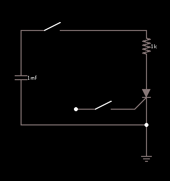
Then you might use its characteristic of staying on once it's on, until current drops to near-zero. Say a capacitor were to discharge through an scr...

5847151800_1352493688.png


The scr will turn off when the capacitor is fully discharged.

Then the capacitor can be recharged from a power supply, if you turn different switches on and off at the proper times.

Maybe sensing volt levels using a comparator or op amp...

I don't know for sure that it can be made to work. But you have to start somewhere.

No one can do it for you, but you already know that.
 

In my humble opinion, a thyristor based sawtooth generator can be expected to use the thyristor itself as bistable component that maintains the oscillation, without additional timing generators or switches.

If we want a linear ramp, the capacitor has to be "charged" by a current source. Essentially, the charging must be below the thyristor holding current. The thyristor can be triggered by a Z-diode, the trigger current must be lower than the charging current.

A typical small thyristor (1 A rated current) NXP BT168 has a holding current of 2 mA and a trigger current of 50 µA (with some type variation). So there's a chance to fulfill the said conditions.

To simplify the circuit, a resistor can be used instead of a current source. If the supply voltage is considerably larger than the ramp maximum (trigger voltage), the ramp will be almost linear.


Yes, I did find that video earlier BUT I can't seem to get a sawtooth scope image in multisim! :s
I'm using a tektronix oscilloscope but even at auto-set the scope-image is a flat line....

What am I doing wrong?

Your explenations and circuits are well apreciated! but I can't seem to set my oscilloscope the right way? DC, AC, XY? any other setting that shows me the right sawtooth?

Thanks for your help all!

@Alertlinks : What is your input signal exactly?
 
Last edited:

Input is 150V DC.
Here is proteus design file.
 

Attachments

  • sawtooth.zip
    11.7 KB · Views: 120
I downloaded and rechecked. Its working.

Any chance you can port it to multisim?, I'm not quiet familiar with Proteus.

I'm trying this myself but I'm failing once again.

EDIT: I noticed your input signal to be a pulse of 150V not exactly DC ? :s I don't have a problem with that since it hasn't been asked but how to do this in multisim?
 
Last edited:

I 'm not quiet familiar with Proteus.
Just open with proteus and push run button. Scope will show input and output traces. I dont have mutisim installed on my computer.
 
Last edited:

Just open with proteus and push run button. Scope will show input and output traces. I dont have mutisim installed on my computer.

Yes, I have the exact output but unfortunately our teachers demand Multisim circuits. Therefor I can not use your circuit as is.

I am glad to see a perfect sawtooth and I'll try to understand your circuit furthermore so I can rebuild it.

If anyone else can help me out with the multisim version? Or another possibility in multisim?

Thnx! and grts

@tpetar : Can you build that circuit in multisim and get a working scope image? :s I can't
 

Sorry my friend I dont waste time on toys and simulators.

Say your teacher to include real oscilloscope and real parts in classroom.

I hope you can adjust multisim to show what you want.

;-)
 

Sorry my friend I dont waste time on toys and simulators.

Say your teacher to include real oscilloscope and real parts in classroom.

I hope you can adjust multisim to show what you want.

;-)

k, no problem, I believe I will try out a few circuits given in class and hope to get a scope image that way.

Thank you.
 

In Multisim,

9572091100_1353577239.jpg
 
  • Like
Reactions: FvM

    FvM

    Points: 2
    Helpful Answer Positive Rating
With a trigger transformer on bottom of C1, it's a classical free running stroboscope trigger circuit.
 

1. Charge a capacitor through a resistor.
2. Thyristors have a breakover voltage, i.e., as the voltage increases, they suddenly start conducting.
3. Connect the thyristor to the capacitor.
4. When the voltage across the capacitor rises above the breakover voltage of the thyristor, it starts conducting and discharges the capacitor.
5. When current less than the holding current flows through the thyristor, it turns off. You'll get a nice saw tooth wave generator with only 3 components. (a few more resistors might be required).

The circuit i've described above should theoretically work and generate a saw tooth wave, i haven't tried it though.
 

Status
Not open for further replies.

Part and Inventory Search

Welcome to EDABoard.com

Sponsor

Back
Top