Continue to Site

Welcome to EDAboard.com

Welcome to our site! EDAboard.com is an international Electronics Discussion Forum focused on EDA software, circuits, schematics, books, theory, papers, asic, pld, 8051, DSP, Network, RF, Analog Design, PCB, Service Manuals... and a whole lot more! To participate you need to register. Registration is free. Click here to register now.

Home made electronic microscope

Status
Not open for further replies.

john-nafp

Newbie level 4
Newbie level 4
Joined
Mar 5, 2018
Messages
7
Helped
0
Reputation
0
Reaction score
1
Trophy points
3
Location
GB
Activity points
96
some time ago i made an electronic microscope for pcb inspection. since there is no video of the construction that time, i made one presenting it and showing how it works.it uses a cheap webcam and old digital camera lens mechanism for zoom-focus.
here is the video of the microscope and some pictures and diagram of the controller.
diagram for the motor driver
Schematic_reverse-polarity.PNG
the switches
ResizerImage4000X2250.jpg
the microscope
Image1.jpg
ResizerImage1920X1080.jpg
the led is powered by a generic boost converter module that converts the 5v from pc to 12v and added a potentiometer to adjust the brightness
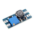
stepup module.jpg
the rest of the construction is made of various metal and plastic parts i had laying around.
at about the end of the video im showing how the microscope performs..
 

Attachments

  • switch.jpg
    switch.jpg
    483.6 KB · Views: 148

Hello john-nafp,
I think you've done an excellent job. Presentation was very good also.
I have to admit that its not the prettiest light microscope I've seen, but
the best thing is that you made it from parts you already had laying
around and you managed to make it work very well. :clap:
Even though a more expensive lens/camera will improve the resolution,
I feel that what you have so far is excellent, and the only thing I would
probably change is the lighting. I would create a ring type assembly with
individual LEDs and mount it around the camera to prevent shadows.
But then again, its only my preference.
Regardless though, I still think you've done a superb job.
WELL DONE dude... :thumbsup:
Regards,
Relayer
 

Very well done. Your enlarged moving images have a wide field of view. (These days my ordinary microscope makes me bleary-eyed from peering in the eyepiece). And you did it with an inexpensive webcam through a magnifying glass from a digital camera.
 

I can say that your project is successful because I can read the letters on the SMD- too much magnification does not get more information and your field of view is quite good. Nothing much can be done about the depth of field and using a better lens or camera will not give much improvement. But the USB output is not sufficient for using a 10W LED light and I suggest you try (i) 4 warm white light source (LED) arranged around the lens and also (ii) 4 UV LED placed next to the white LEDs. You can select UV or white LED using a switch and sometimes you will get better results in UV.
 

I would also like to congratulate you.

It shows that a little ingenuity and dedication goes a long way. Your project shows both

:thumbsup:
 

thank you all for your nice words..i must say that i tryied different types of illumination and a ''ring'' type pcb with leds around the camera but the result was not satisfying for me,to be able to read the letters on the smd components you must find the right angle to lit the object, so i used a 10w led on a bracket that can be moved in various positions and that gave me the best results..also a higher resolution(more expensive) webcam would give more detailed video and better frame rate.although the video that shows how the microscope performs is done with a screen capture software and then re encoded for editing and again re encoded by youtube when uploaded it.
 

Status
Not open for further replies.

Similar threads

Part and Inventory Search

Welcome to EDABoard.com

Sponsor

Back
Top