Continue to Site

Welcome to EDAboard.com

Welcome to our site! EDAboard.com is an international Electronics Discussion Forum focused on EDA software, circuits, schematics, books, theory, papers, asic, pld, 8051, DSP, Network, RF, Analog Design, PCB, Service Manuals... and a whole lot more! To participate you need to register. Registration is free. Click here to register now.

Home built battery pack frying 12v -> 110v inverters

Status
Not open for further replies.

bignose

Newbie level 3
Newbie level 3
Joined
Aug 28, 2012
Messages
4
Helped
0
Reputation
0
Reaction score
0
Trophy points
1,281
Activity points
1,316
Hi,

I built a little battery pack in a .50 cal machine gun ammo container. Its 3 6amp hour 12v batteries with a charge controller, a switch and a 30 amp fuse. I charge it with about 8 sq feet of solar panels.

It works fine for running things like motors or lights. (A small fan for example), however when I put a 12v to 110v inverter on it, it tends to fry the inverter.

I've checked for shorts etc.

Tips?

I can provide wiring diagrams if necessary.
 

Make sure you are getting 12v out of your batteries. I'm assuming you are using a car port type inverter? And the inverter fries on no load correct?


you can use lm338k, its a adjastable regulator wich can easily deliver 12v@5A, a pack of 5 cost $5 in ebay.
your battery is deep cycle?
 

My batteries are old cells from a salvaged UPS system :)
 

it is good that you used ups batteries because they are deep cycle, but they may have been overused in the past, and maybe they cannot provide those ampere hours. and it is not so good to connect the all together in parallel ( personally i have them seperated. they can be seperated with diodes or with a good charge controller )

(this has nothing to do with your question:) Do you use a charge controller ?
I could help if you want, i have also solar panels in my trailer :D
 

Your solar panel give higher voltage, and this is cause of smoking in inverter, not battery. Check solar panel regulator-controller adjust oltage on it if possible or change it.

Try inverter without solar panel connected to battery.

Check input voltage range for inverter.

Check how solar regulator-controller works, meassure voltage, monitor that battery is not disconnected under low voltage.
 

Did inverter work ok before on a car 12~14.2V?
Check specific gravity which is an indication of capacity and ESR of each cell. High ESR can cause issues with some inverter designs causing instability during boost pulses.

I don't know if it needs a low ESR cap in parallel with battery to reduce VI transition losses from spurious switching, but depends on AC ripple on battery during load.
 

Maybe battery is very bad what sayed Thebadtall, and regulator-charger disconnect bat from circuit under low voltage, and we have small smoked fried potatoes in inverter. :smile:
 

I don't actually recall if the intevertor fried (I'm using that as a figure of speach, it actually just stopped working. no smoke) when the solar panel was hooked up or not. I do recall that yes it did work when plugged into a car. And I know when my solar panels are hooked up i see around 20 volts, so its possible that 20 volts went straight to the inverter. I will do another test on another invertor without any panels setup.

I do use a charge controller so I'm safe on that side.

If I was to hook up one of these : https://www.ebay.ca/itm/5pcs-LM338K...ltDomain_0&hash=item3f0a2a738c#ht_2623wt_1156 , is it just a matter of splicing one into a wire on both of those "holes"?
 

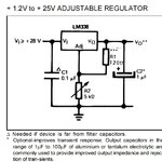
in my post, my mistake, did not mention that this is a part of a regulator circuit.
this is the IC of the regulator, you would need some more parts, and a soldering iron to make the circuit
asdasd.jpg

if you would not like to make the circuit, you can get a cheap charge controller $12 like this
https://www.ebay.ca/itm/10A-20A-30A...t=LH_DefaultDomain_0&var=&hash=item5f7ccd423e

wich can be connected to the inverter,solar panel and battery at the same time.
 
  • Like
Reactions: tpetar

    tpetar

    Points: 2
    Helpful Answer Positive Rating
I don't actually recall if the intevertor fried (I'm using that as a figure of speach, it actually just stopped working. no smoke) when the solar panel was hooked up or not. I do recall that yes it did work when plugged into a car. And I know when my solar panels are hooked up i see around 20 volts, so its possible that 20 volts went straight to the inverter. I will do another test on another invertor without any panels setup.

I do use a charge controller so I'm safe on that side.

If I was to hook up one of these : https://www.ebay.ca/itm/5pcs-LM338K...ltDomain_0&hash=item3f0a2a738c#ht_2623wt_1156 , is it just a matter of splicing one into a wire on both of those "holes"?

In your solar system you must always have battery connected to regulate voltage, and must have charging regulator which regulate voltage and charging. Also battery must be good not some battery removed from Jeep Williams WWII with leads 70 years old. :grin:

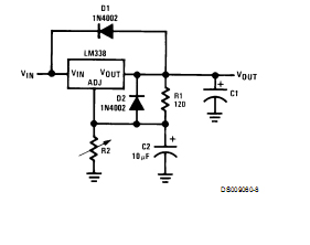
Thebadtall give you nice idea for regulating voltage, also LM338K have current limiting up to 5A. I use lots of LM338K they can be damaged on polarity reverse, that means that is nice to include some diode for this purpose.

reg%2520copy.jpg


Use LM338K TO-3 not LM338T TO-220, both are 5A but TO-3 can dissipate more power.
 
Last edited:

the battery op power in no load may be sound so try to regulate it as well as try to check its source resistance if the source drop is low then the open ckt voltage may not be truly reliable

chk if the op voltage in the loop is the same as the rated voltage you found in open condn

then as others have said go for a regulator for stable op voltage
 
  • Like
Reactions: tpetar

    tpetar

    Points: 2
    Helpful Answer Positive Rating
Status
Not open for further replies.

Similar threads

Part and Inventory Search

Welcome to EDABoard.com

Sponsor

Back
Top