Vermes
Advanced Member level 4

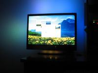
The device is based on a single-chip microcontroller Atmega16 and a tri-color LED kit. The device consists of a controller and diode modules connected to it, three LEDs connected in parallel. Ambilight has 8 independent channels that generate the colors according to the average color at the edges of the screen. It also has an additional output for the last channel, so two modules can be connected at the bottom of the screen. USB interface provides the PC connectivity via the built-in converter USB ↔ RS-232 (FTDI). Control software was written in Python and runs successfully on Windows and Linux (it was tested on Archilinux and PLD Titanium, 64-bit versions). The control program allows to define areas of averaging the color for each channel and configuration of the colors pass speed, needed when the screen changes very quickly. Additionally, the device is able to receive transmission RC5 and control the movie player.
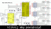
The main element of the controller is microcontroller U1 (Atmega16) with the quartz resonator X1 (16MHz) and capacitors C1 (22pF) and C2 (22pF). Prog connector allows to program the microcontroller without removing the processor from the base. System U3 (FT232RL) is an USB-RS232 converter. It provides trouble-free operation under all operating systems and correct transmission by USB. Both the software and hardware, its support is identical to the serial port. USB1 connector is classic USB B socket, used in most computer hardware. Capacitors C9 (10nF), C10 (100nF) and C11 (4,7uF) filter the supply voltage for the system U3. Resistors R4 and R5 are helpful when testing connection the cable to the USB port, because the whole system is powered from an external 5V power supply. R4 pulls the microcontroller port state to the mass potential as the plug is undone, and R5 prevents the CPU power supply through the outlet of the port when the external power supply is disconnected. Resistors R2 (4,7k) and R3 (10k) are responsible for matching logic levels between 5V and 3,3V standards (normal resistive divider) and the control of the reset input of U3. Thus, regardless whether the USB will be plugged firstly and then the power or vice versa, the computer detects the device correctly in the system. Connector Z1 is a place to connect 5V power supply, usually directly from the power supply in the computer, because such a number of LEDs can in extreme cases, charge current greater than 1,6A. Capacitors C5-C6 (100nF) and C3-C4 (100uF) filter the supply voltage. Diode modules have a common anode. U4-U6 systems (ULN2803) are used in output buffers. Channels are connected to the controller with 10-wire tapes through popular connectors FD10 and plugs FC10 (FC1-FC8, FC8B). Such a large connector was chosen for its ease of installation of such tapes, and no need to solder the wires. In case of processing or replacement of a channel, simply pull the plug. Resistor R1 (220R) and capacitor C7 (100uF) are the power supply circuits for infrared receiver U2 (TSOP1736).
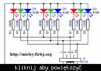
Diodes D1-D3 made in SMD technology are key to the smooth operation of the system. Scattering of colors in these diodes is much better than the equivalents for hole mounting. Resistors R1-R9 limit the current of individual LED structures. R1, R4 and R7 (180R) have a lower value to ensure equal illumination of all colors (seen by the eye). Other resistors have a value of 330R. Values of those elements can be changed, depending on the diodes used, so as to provide adequate current for each LED structure.
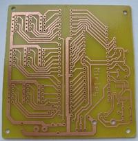
Installation of the controller is not so easy because of the presence of the system in a very small housing SSOP28. You have to be very carefully while making the board, and then soldering the system, paying attention in order to install it correctly (use the assembly drawing reflected in a mirror, because the system is from the bottom). In the second step, solder all the 6 jumpers and resistors. It is good to give a stand at the circuit U1, as under the buffers U4-U6. The order of the remaining elements is arbitrary, except that the connectors FD10 should be mounted at the very end.
Implementation of boards with LEDs requires the use of a thin laminate, such as 0,8mm, because then you can slightly bend the channel and adjust it to the curvature of the monitor. Installation of LED panels (9 pieces) is not difficult but time consuming as it requires many components soldered. In this case, there are many mounting options. You can solder the resistor classically from the elements side, and the LEDs on the side of paths, or place all the elements on the side of paths, as shown in the photos. Connector for tape (angle) must be soldered to the PCB from the print side, what requires little skill and a thin tip of soldering iron. Besides, installation of boards with LEDs will not cause any problem.
Photos:
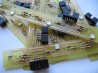
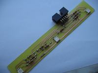
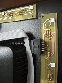
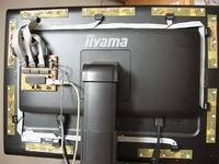
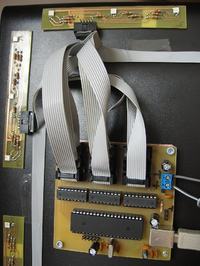
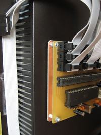
The device does not need any housing, and the boards can be attached to the monitor by mirror tape (super strong double sided tape with foam structure). For this reason, LED panels boards should not have any resistors on the elements side. This allows easy gluing them on the monitor. Additionally, a thin laminate, of which LED panels were made, allows fitting the shape of the board to the curvate of the monitor's back.
After the system hardware is done, download the software: https://github.com/downloads/grizz-pl/mirlight/winexe_mirlight08beta.zip.
Link to original thread (many attachments) – Mirlight 2 (Domowy Ambilight o ulepszonej konstrukcji)