Vermes
Advanced Member level 4


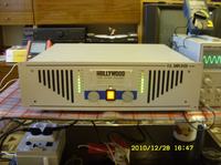
The assumptions of this project was to make a useful power amplifier with a power of approximately 2x200W/4ohm. The device was to be cheap and not complicated, has an original look and light weight.
Parameters:
- output power: 2x150W/4ohm, in bridge: 1x300W/8ohm
- input sensitivity: 0,7W, 10kohm
- operation: switch – bridge/stereo
- delayed switching the speakers
- protection against DC at the output
- disconnection of outputs in case of short circuit and temperature exceeding 90 degrees Celsius
- fan control dependent on temperature (max. rotations at 60 degrees Celsius)
- LED meter with CLIP indication
- two-state LED indicator: red (protection works)/yellow (ready to work), indicating the operation state of the amplifier
- switch: GND/LIFT, shorting the signal ground with the protection cable of the grid
Housing:
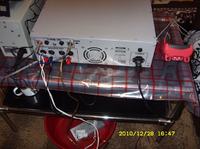
A housing from an old China amplifier was used as a housing to described here device, due to the fact that the solution is very cheap and easy to use, it also looks okay. Components of the housing, except the speaker sockets speakon, modified meters, the transformer's mount and knobs for potentiometers, were changed to new ones. The housing was also reinforced with angles on the rear wall.
Power amplifier:
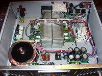
The power amplifier is a classic holton system based on transistors IRFP240/9240.
Main power supply and softstart:
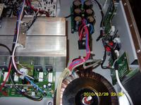
It is also a classic application and ALTRONA boards. Filtering capacitors 3x4700u/63V per rail. Bridge with plenty of 35A, screwed to the housing. 2x40V AC – 500VA, also with a very wide margin and additional windings (powering auxiliary systems).
Control – protection system:
It is a „fully transistor” system (except the fan rotations controller) – simple, well operating, without unnecessary operational amplifiers. Two optocouplers PC817 per channel seek for a short circuit. They detect drops of voltage on low-ohm resistors in final transistors. In addition, the system has a not stabilized auxiliary power supply, which supplies relays of the outputs, indication diodes, drive and fan. Temperature sensor is bimetallic switch and NTC thermistor on heat sinks.
Phase inverting circuit:
The phase inverting circuit is made on two operational amplifiers OP07 and is powered from the main power supply of the power amplifier.


Link to original thread - Końcówka mocy Hoolywood - Po mojemu