Continue to Site

Welcome to EDAboard.com

Welcome to our site! EDAboard.com is an international Electronics Discussion Forum focused on EDA software, circuits, schematics, books, theory, papers, asic, pld, 8051, DSP, Network, RF, Analog Design, PCB, Service Manuals... and a whole lot more! To participate you need to register. Registration is free. Click here to register now.

High Side switching using P Channel

Status
Not open for further replies.

tiwari.sachin

Full Member level 6
Full Member level 6
Joined
Aug 1, 2009
Messages
341
Helped
3
Reputation
6
Reaction score
3
Trophy points
1,298
Location
India
Activity points
4,449
I am using LTC4412 for power path switching

I have auxillary input (DC Jack) - 9V

Battery: 2 Cell Li Ion


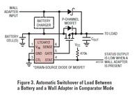
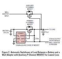
In the example, it shows use of P Channel with Drain connected to Positive and Source to load.

I understand that this would avoid reverse flow but shouldnt the voltage input be connected to Source of MOSFET

I am trying the following Circuit


Mosfet: FDS4935BZ

Load current: Max 3 amps


Results:

When only Battery Connected (eg 7.4, SAY BV): Output is 7.4V

Battery removed from the circuit and When Auxillary Power Connected (9V SAY AV): Output is 9V

When Battery is present and I connect Auxillary Power,

Out is 9V (As expected)

But the battery voltage also shifts to 9V (which should not be the case)

BV Present, AV Absent: Output is BV
BV Absent, AV Present: Output is AV
BV Present, AV Present: Output is AV but BV increases to 9V which shouldnt be the case :(

BV Present, AV Present
I tried reducing AV, the voltage at the battery stays at AV as long as AV == BV, after that BV stays at 7.4V and output is also 7.4V


I hope I am able to make things clear :)

- - - Updated - - -

Any other option for power path management should also be ok, provided there is no drop at output, especially from battery, hence using diode oring is not and option
 
Last edited:

Hi,

But the battery voltage also shifts to 9V (which should not be the case)
For this case:
Pleas tell us the voltage of pin5 (gate).


Klaus
 

When BV = 7.4V and AV is turned ON (9V)

Output at PIN 3 of MOSFET is 9V and BV also shoots to 9V

Pin 5 of LTC4412 has 3.47V

When i remove/turnoff AV

Pin5 of LTC4412 drops to 2.9V and PIN 3 of MOSFET has 7.4V and battery also slows 7.4V
 

Review the datasheet to understand LTC4412 operation principle.

It needs a voltage difference of up to 32 mV between Sense and Vin to disconnect the battery. If the MOSFET has very low Rdson and/or the battery high internal resistance, the switchover won't work.
 

Hi,

Pin 5 of LTC4412 has 3.47V

It should be either 0V or V_out. 3.47V is no valid level. Check your circuit.

Klaus
 

FvM and KlausST... I shall check the same

Meanwhile shouldnt MOSFET source be connected to positive. Just a a bit curious why its done that way
 

Meanwhile shouldnt MOSFET source be connected to positive. Just a a bit curious why its done that way
It must be connected as it is, otherwise the substrate diode would short the switch.

The transistor is in fact reverse operated, no problem for a MOSFET.
 

Was wondering if the following schematic be useful, atleast till I am able to find the issue with LTC part.


What worries me is the connection of battery at drain. Will I be able to provide 3 amps needed for the load??
 

Hi,

i hope this is not related to LTC4412....

There are a lot of issues.
* it will not fully switch ON battery --> a lot of dropout.
* when auxilary is ON, then battery current flows through bjt...


What worries me is the connection of battery at drain
As FvM said: the FET works in both directions. Don´t worry anymore.

Klaus
 

Hi,

i hope this is not related to LTC4412....

There are a lot of issues.
* it will not fully switch ON battery --> a lot of dropout.
* when auxilary is ON, then battery current flows through bjt...


As FvM said: the FET works in both directions. Don´t worry anymore.

Klaus

Pls neglect my last reply... I just realised it was such a bad choice... really bad one... I missed the internal diode completely... My mistake


I am somehow not able to figure out a simple solution for switching :thinker:
 

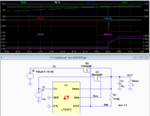
Below is an LTspice simulation of your (slightly modified) circuit.
It seems to work properly. Notice that I(v1) drops to zero when V2 takes over, indicating no feedback from V2 back through V1.
Note that, due to the limited (10 microamp) sink ability of the STAT output, I increased the value of R1 to 1 megohm so that the output would go to near 0V when V2 is active.
What is the difference between your circuit voltages and the simulation?

Switchover.PNG

- - - Updated - - -

Edit: After some further though I believe that the low value of R1 (the resistor between Sense and STAT in my simulation schematic) is likely your problem.

Increase its value to 1 MΩ or so and see if that helps.
 
Last edited:

A requirement for successful switchover is a sufficient low battery impedance. It's of course achieved with a voltage source representing the battery.
 

A requirement for successful switchover is a sufficient low battery impedance. It's of course achieved with a voltage source representing the battery.
I tried the simulation with a 1 ohm V1 battery source (high for a battery) and the circuit still did the switch-over properly.
 

Yes, with reasonable MOSFET parameters. As said, the controller needs to sense up to 32 mV difference voltage across the FET. If you select a MOSFET far below 10 mohm Rdson, 1 ohm battery impedance can be too much. The same with a much higher battery impedance.
 

Yes, with reasonable MOSFET parameters. As said, the controller needs to sense up to 32 mV difference voltage across the FET. If you select a MOSFET far below 10 mohm Rdson, 1 ohm battery impedance can be too much. The same with a much higher battery impedance.
The MOSFET ON resistance or battery impedance value is actually of little consequence as far as the circuit switch-over is concerned.
The circuit operation is a little tricky.
It operates in the linear mode where it adjusts the gate voltage of Q1 to keep its Vsd no lower than 20mV.
When the auxiliary voltage comes up and starts to conduct through the body diode of Q2, the current through Q1 will start to drop by the same amount.
This cause a reduction in Q1's Vsd. This is detected by the Sense line which then raises Q1's gate voltage in an attempt to keep the drop across Q1 at least 20mV.
This continues until Q1 is cutoff, at which point the STAT line goes low, turning on Q2.
You can see this occurring in my simulation.
So this shows that, even if the Q1 MOSFET has zero ON resistance, and/or the battery impedance is high, the circuit will still switch over properly because of the way the device works.
 
Last edited:
  • Like
Reactions: FvM

    FvM

    Points: 2
    Helpful Answer Positive Rating
Yes, I misunderstood the circuit operation. Thanks for insisting.

Means switchover would occur even with a very high impedance battery. There must be some hidden fault in the originally described circuit.
 

Yes, I misunderstood the circuit operation. Thanks for insisting.

Means switchover would occur even with a very high impedance battery. There must be some hidden fault in the originally described circuit.
I think the problem (as noted in my post #11) was the fact that the STAT line can typically only sink 10µA (6µA worst-case) which means the STAT line wasn't going to zero with the 470kΩ shown in the data sheet schematic with a 9V supply (apparently that value was designed for a less then 5V supply switch-over or the data sheet writer missed that IC limitation).
But I never heard back from the OP if he tried a 1MΩ resistor as I suggested so I don't know for certain if that was his problem. :???:
Actually for a worst-case value of 6µA with a 9V supply, the resistor should be no smaller than 1.5MΩ.
 

crutschow... I will try it on monday and update you... We have some strikes going on here and unfortunately our office is closed too... We had to do it for security reasons... Compulsion order from police :(

First thing on monday is to test the circuit...
 

I am trying the following schematic (Since a little drop when DC jack Connected is ok)


Results:

When Battery is not connected

Gate voltage is 0V when Auxillary Not connected (obvious)
Gate voltage is 9.4V when Auxillary connected


When Battery Present

Without Auxilary (Adaptor): Output = 7.77V, while battery voltage is 7.91V and voltage at gate is 7.77
STAT: 3.26V

With Auxilary (Adaptor): Output = 9.32, while adaptor output shows 9.43 and voltage at gate is 9.14
STAT: 130mV


The Mosfet isnt turning ON as the gate voltage never goes to 0V

Diode used: SS14

Vcc = 3.3V as I want to connect to the MCU to know if auxillary is connected

Pullup on stat PIN: 330K (301K and 28.7 in series)

I havent used output capacitor as of now and the output is connected to the CRO


Note: I have not used battery charger section as of now but will do that later

- - - Updated - - -

Battery Impedance is around 250mOhm

I tried 470K and yet same results
 
Last edited:

Hi,

1) no capacitor --> connect a capacitor.

2) no charger circuit --> then use a 100k ohms resistor from SS14 anode to GND to prevent floating signal

Klaus
 

Status
Not open for further replies.

Similar threads

Part and Inventory Search

Welcome to EDABoard.com

Sponsor

Back
Top