Continue to Site

Welcome to EDAboard.com

Welcome to our site! EDAboard.com is an international Electronics Discussion Forum focused on EDA software, circuits, schematics, books, theory, papers, asic, pld, 8051, DSP, Network, RF, Analog Design, PCB, Service Manuals... and a whole lot more! To participate you need to register. Registration is free. Click here to register now.

HFSS - why does the antenna design kit's Quadrifilar Helix Antenna have 4 excitations

Status
Not open for further replies.

DeboraHarry

Full Member level 5
Full Member level 5
Joined
Dec 3, 2011
Messages
274
Helped
48
Reputation
94
Reaction score
43
Trophy points
1,308
Location
UK
Visit site
Activity points
3,905
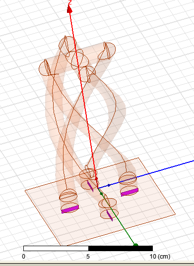
If you use the free Antenna Design kit for HFSS it has the ability to design a number of differnt types of antennas. One antenna puzzles me though. The Quadrifilar Helix Antenna has 4 excitations. In the diagram below, the ports have been highlighted.
92_1339356242.png


I can't see why this antenna should have 4 ports. Am I missing something?

Deborah
 

where can you see it is free ? Link ?

antenna design kit was free before this but nowadays its not free

If you use the free Antenna Design kit for HFSS it has the ability to design a number of differnt types of antennas. One antenna puzzles me though. The Quadrifilar Helix Antenna has 4 excitations. In the diagram below, the ports have been highlighted.
I can't see why this antenna should have 4 ports. Am I missing something?

Deborah

and about helix question ,i cant understand your problem
 

antenna design kit was free before this but nowadays its not free

and about helix question ,i cant understand your problem

I believe the antenna design kit is a free download, but you have to have HFSS to get it free. So perhaps "free" was not the right word.

As for the antenna, one would normally expect there to be a single port where one drives it - not 4 of them. If you drive one of the 4, in order that the analysis in HFSS to be correct, I assume you would have to terminate the other 3 ports in 50 Ohms, since that is what they are set to currently. That would almost certainly mean the antenna has low efficiency, with 3 resistors in there.

It's not normal for an antenna to have 4 ports. Antennas usually have 1 port, amplifiers have 2, directional couplers have 3 or 4 (dual directional coupler).


Deborah
 

that's not true may be an antenna has two or four port u can use antenna magus too for design
i attach some thing may be helpful for u
 

Attachments

  • The Quadrifilar Helix Antenna.pdf
    795.2 KB · Views: 295
  • qha.exe
    236 KB · Views: 149

that's not true may be an antenna has two or four port
Agreed, but it is not usual. I can't think of any antenna designed for a single frequency where there will be more than one input port. For this particular design created by the HFSS antenna design kit, I have absolutely no idea how one is supposed to use it. If I had a GPS receiver for example, why would one connect it?[/QUOTE]

u can use antenna magus too for design
i attach some thing may be helpful for u

Thank you. Where did it come from? It looks interesting, but without the references, it is less useful than it might otherwise be. I find figure 22-8 confusing. The text "Centre connected to opposite element" is confusing to me. Whilst I can see where the antenna is fed from, where the coax first goes to the left, then then to the right, then goes left to the centre, at that point I'm confused exactly what is connected to what. I think the other part, despite being shown the same outside diameter as the coax, is in fact solid, and not coaxial. So the centre of the coax is fed to a straight piece of wire. At least that's what I think - I'm not 100% sure.

But note figure 22-8 only has a single feed point with coax.

As for figures 22-9 and the photo in 22-1, I really have no idea how the feed is arranged. The photograph does not (to me at least) provide any help on how the two loops are connected. It only shows to me there are two antennas, one a big bit bigger than the other, and their size is quite small compared to a pen.

The design I posted was not created by Antenna Magus, which is an expensive commercial product. (I have seen a copy, and thought it of limited value, as it is too inflexible to be of much use. I'm amazed they manage to sell Antenna Magus. The design I posted was crated by the Antenna Design kit for HFSS, which is a free download if you have HFSS. In fact, if you don't have HFSS installed, the product will not install itself. What I see in HFSS is 16 S parameters. S11, S22, S33 and S44 are such the return loss is good on each. But it's not clear to me how you excite these 4 ports such that the return loss remains good and it has a decent radiation pattern. Clearly if you excite port 1, whilst ports 2, 3 and 4 are terminated in 50 Ohms, the return loss at port 1 will be good. But if you excite two ports, then that wont necessarily be so, and you need to have some idea on how to excite them (phase relationship between them). None of that is clear from the antenna design kit.

Deborah
 

The quadrifiliar antenna has each element driven a progressive 90 degrees in phase. In the project, go to HFSS -> Fields -> Edit Sources and you will see this relation, which makes sense for a CP excitation as one would expect from this structure.

Have Fun
 
The quadrifiliar antenna has each element driven a progressive 90 degrees in phase. In the project, go to HFSS -> Fields -> Edit Sources and you will see this relation, which makes sense for a CP excitation as one would expect from this structure.

Have Fun


Thank you, that was most helpful.

I'm sure I've seen variations of this antenna which don't need something to split the power 4 ways, while providing a 90 degree phase shift between them. i.e. there are versions which have just one feed.
 

Status
Not open for further replies.

Part and Inventory Search

Welcome to EDABoard.com

Sponsor

Back
Top