HF Power amplifier designing

Status
Not open for further replies.

hirashah

Newbie level 4
Newbie level 4
Joined
Dec 29, 2010
Messages
5
Helped
0
Reputation
0
Reaction score
0
Trophy points
1,281
Activity points
1,314
Hi, I m making an power amplifier from 1-30Mhz which gives output of 600 watt, I m using ADS software and using transistor MRF422 , but there is problem in getting gain in the required range (images are attached), so can anybody help, telling me where could be the problem?


Secondly to get 600watt i would used power divider and combiner but they are not available in ADS, so how could i make them on ADS?

Regards.
 

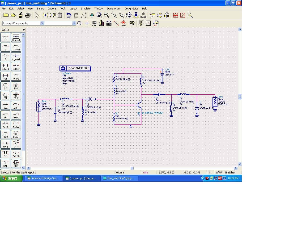
Try not to specify component values to 6 decimal places, it just clutters up the drawing. I think the 50 ohms (R2) is soaking up the drive power. I would work on .55V foward bias so R1/R2 = 27.5/.55 with R1 400 ohms. Now the input circuitry can be used to match 50 source Z to whatever you think the transistors input impedance is. I do not see the need for the inductor in series with R1, it would be better in series with R2. The output circuit, 600W @28 V, actually 56V p-p or 600W @20V rms = ~30 A, the collector impedance is about .7 ohms, so you are trying to match this to 50 ohms using two sections, so each section must be a 1:8 transformation. So design two PI networks Zin = .7, Zout 5.6 ohms and 5.6 in and 50 out. Obviously, the "centre" capacitors can then be combined.
Frank
 
Off topic:
I think since it is just a simulation, it doesn't matter trying to get 600W output that is 4 times the minimum rated one (150W) of the RF power transistor of interest.

Kerim
 

Status
Not open for further replies.

Similar threads