Continue to Site

Welcome to EDAboard.com

Welcome to our site! EDAboard.com is an international Electronics Discussion Forum focused on EDA software, circuits, schematics, books, theory, papers, asic, pld, 8051, DSP, Network, RF, Analog Design, PCB, Service Manuals... and a whole lot more! To participate you need to register. Registration is free. Click here to register now.

Help with RF circuit encoder/decoder troubleshooting

Status
Not open for further replies.

comptonrj

Newbie level 3
Newbie level 3
Joined
Jun 21, 2018
Messages
3
Helped
0
Reputation
0
Reaction score
0
Trophy points
1
Activity points
61
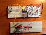
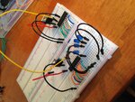
I know there are many threads here on this topic, but I am posting photos of my specific circuit. I have looked at multiple tutorials and troubleshooting tips, scoured the data sheets, checked and rechecked and I can't seem to get this thing to work. So, following the advice of one tutorial I have set up a test for just the HT12E encoder and the HT12D decoder. They are physically connected via wire. In the tutorial the LEDs lit up when pins 10-13 of the encoder were left open. I get no signal from the LEDs. I have swtiched out both encoder and decoder for new replacement parts, I have tried different variations for the oscillation resistors (right now they are 33k for the decoder and 750k for the encoder), and flipped the pins on the LEDs. I am getting a voltage reading thru all components except the decoder. I get 5V from pin 18 to pin 9 on the encoder. Strangely I get about 3.7V from the in to the out on both voltage regulators.

Can anyone help me out? I am sure its a stupid mistake.

Ryan image (2).jpgimage (1).jpgimage.jpg
 

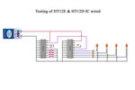
Thanks for the response. Here is the schematic. The reason I posted the breadboard was in case there was a discrepancy between my actual circuit and the schematic. schem.JPG
 

The wiring on the breadboard is a mess. How can you see what is wrongly connected?
Aren't the contacts on the breadboard intermittent?
I always solder parts and a few short, straight jumper wires on a neat stripboard layout where every connection can plainly be seen and everything works properly.
 

This is all just a mess. Aside from the ratsnest of wires, you speak of some voltage regulators that don't appear anywhere on your schematic. Put a little more effort into your assembly and your post.
 

Hi,

I can't detect a single capacitor, neither at the voltage regulators, nor at VCC of the ICs.
The pushbuttons are not connected.

Klaus
 

Hi,

besides Klaus's important observations - capacitors are necessary and the regulators need them for stability. Check the datasheet, it's 0.33uF (330nF) at the regulator input and 0.1uF (100nF) or 1uF or 10uF if you so feel the need - but probably no further than 0.1uF or 1uF for your circuit.

Pushbutton thing in the photos is a bit weird there - they were originally connected and you removed them for the photo?

Also, photo 3 row 60 of the breadboard - Is the regulator output cable (black in the photo) actually in the IC VDD pin row or in the row next to it and doing nothing? - That's an easy mistake, breadboards look like the wires are in the right place until three hours of failure and you notice x cable in the wrong row that looked right, that or shorted rows/strips in the breadboard or broken components are good for time-wasting trouble-shooting and confusion followed by anger à la Bob Widlar (Where's the sledgehammer?!!).

I wanted to suggest that when breadboarding and perhaps getting flustered, stick to wire colour-coding always no matter how bad things are, discipline before panic solves problems quicker (e.g. red = VDD/V+; black = ground/0V; signals = separate colours where possible and following a logical path: green in, green out for signal A, blue in, blue out for signal B) otherwise it just makes everything 100 times worse and the black V+ wire is confusing to oneself even, maybe.
 

Hi again,

3.17V... - I'm assuming you are using 5V standard linear regulators like the LM7805 (not an LDO-type regulator) and the battery is like the picture: a weak 9V "brick". You may find that if something is drawing a "lot" of current by design or by accident, the battery will last about 5 minutes before it's useless/wasted. If you can, get a plug-in power supply, you and your finances will appreciate it soon. It may be that a battery like that is not up to the job and using a battery with far less pathetic mAh such as AA batteries in series or a Li-Ion one could help.

Personal experience has been that 7805 regulators not regulating at all/having an abnormally low output voltage is a) incorrect wiring, b) a short or overcurrent somewhere on the circuit dragging the voltage down to current-limiting point, c) not respecting the 2 to 3V dropout voltage above the regulator output voltage these regulators need to operate correctly. I've never had a 7805 break and I have accidentally done some pretty embarrassing things to them occasionally.
Firstly, and I may be very wrong, I'd ditch the battery for a plug-in supply; if the problem persisted, I'd go removing connections on the board one by one until the regulators or at least one regulator started functioning normally and as expected. Good luck! As you say the input and output voltage is 3.17V, I'd blame the battery first then look for shorts on the board.

One more suggestion: The loop antennas on the breadboards are like pretty rainbows and I tried to spot a unicorn and some elves in there but they're missing, I think, anyway look up the term "rats nest" in PCB design and see the similarity ;). For those LEDs, I'd ditch the jumper wires and use the resistors as the wire instead, and connect the LEDs directly from the resistors to ground - already looking neater/cleaner! I'd put one wire to ground from one pushbutton, then make tiny 2-3 cm jumpers between the other pushbutton ground input pins and that wire/first pushbutton pin. I'd also move the regulator on the second board to an intuitive and logical place, i.e. next to VDD, not on the other side of the IC and having the wires criss-crossing other pins completely unnecessarily. I'd also tie as many ground points to the supply/battery ground input point as possible without creating another rats nest or several 2cm ground leads and then a 1 metre one in the process.

As your photos are of the unpowered circuit and I don't know about the HTs besides a good look at the datasheets and other threads related to these popular ICs. If when powered, the LEDs are on by default - which I doubt - that's already 40mA doing nothing but draining a tiny battery, fyi and something to ponder perhaps.

Good luck with the trouble-shooting and getting it to work.
 

You said you get 3.7V from the input to the output of both voltage regulators that might be normal if the battery is brand new, the regulators have the required input and output capacitors and the regulators are 5V ones. 9V battery minus 3.7V= 5.3V so maybe the battery has dropped 0.3V or the regulators are actually 5.3V.
 

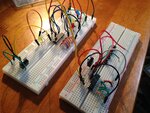
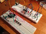
Hello everyone, thanks for the responses. Sorry the wiring was so messy I am new to this whole thing.

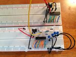
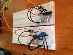
I have tried to clean up the wiring. I don't have enough short red/black wires so I know its still not perfect. The long wires, I know, aren't the best.

image (3).jpg
image (4).jpg
image (5).jpg

I wanted to give a little more info. The original circuit I posted was a reduced form of the full circuit I want to accomplish. It was reduced in order to to isolate just the encoder/decoder for issues. Here is the full circuit I want to accomplish:

https://circuitdigest.com/electronic-circuits/rf-controlled-robot-without-microcontroller

Diagrams here:
full ckt 1.JPG
full ckt 2.JPG


In response to the issues with the voltage regulator:
1.) It is a 7805
2.) I did read about the requirements of the capacitors in the data sheet. Since I didn't have them on hand I was hoping to get it to work since I had seen videos of folks getting their circuit to work without them. However, at this point I am going to order them just to make sure that's not the issue.
3.) In the circuit I just linked to above, the creator doesn't use the capacitors and it seems to work for him which is why I was hoping to get away without them. I had read elsewhere that they are only necessary if the regulator is more than 25cm from the source and they are for the purpose of reducing noise.
4.) Although I only get 3.7V out of the regulator I get the proper 5V from the power source pin to the ground pin (18 to 9) on the encoder. That seems odd to me but I guess the IC is getting the proper voltage.

I am not getting any voltage across the decoder or the voltage reg. of the decoder circuit. I get good connectivity on the data wire between the boards. So I feel like something is off with the decoder. I have switched the part out 3x times now with no luck.

Also as far as the plug-in supply, once again the guy in the link I posted gets his to work in the video with a 9V. I checked both batteries and they are still outputting 9V.

Lastly as far as the encoded data pins (10-13) on the encoder and whether leaving them disconnected keeps the LED's on. Here is the video for the trouble shooting tutorial. Right at 8:45 you can see him turning the LEDs on and off, but it does appear that they are on when those pins are not grounded.

https://www.youtube.com/watch?time_continue=669&v=-MqxYCW5vco

At the current juncture I will wait to see if the capacitors help, but still not getting any response on the decoder board. Given that both tutorials I have posted here get the circuits to work without the capacitors, what other problems could be going on here?

Once again thanks to everyone for taking to time to help me out.
 

How can you get 5 volts at the encoder, but only 3.7 at the regulator? According to the schematic they are the same point.so you either measured something wrong, or you've got some defective wiring. And I don't think the cap on the regulator matters too much.

And I HATE those white breadboards, they're nothing but trouble. And they MOST CERTAINLY are not designed to accept the leads of a TO-220 (7805).
 

Hi,

I was hoping to get it to work since I had seen videos of folks getting their circuit to work without them.
Don't design electronics with "hope". Read datasheets and follow the rules.

'I have seen..." there is so much crap information in the internet.
--> Look for reliable informations from the IC manufacturers. They usually provide a lot of informations besides the datasheets in tutorials, application notes, videos, software....

Klaus
 

Hi,

Besides no doubt unrelated to the problem here, I must be misunderstanding the datasheets about the oscillator frequencies. Maybe if the encoder is set at about 3.75kHz with the 750k resistor and the decoder has to be approximately equal to encoder frequency/50, try 220k to 330k on the decoder, it should give a very, very loose ~400Hz or so. If you haven't already tried. The graphs to decipher are page 6 and page 9 of the HT datasheets (the copies I have, at least). 33k at 5V gives about 2kHz on the decoder, again, if I've understood the datasheet oscillator resistors criteria correctly, that certainly isn't Fosc encoder/50. Please correct me if that understanding is wrong, of course.

You have somehow harnessed free power via the 7805 - it wirelessly transmits 5V to the encoder from only 3.7, incredible... :) Are you sure you are measuring that correctly (because the breadboards look correct, to me)? I'd stay well away from placing ground lead from DMM on one breadboard and measuring a positive voltage on another breadboard - it may give erroneous results.
 
Status
Not open for further replies.

Part and Inventory Search

Welcome to EDABoard.com

Sponsor

Back
Top