mcmsat13
Member level 5

Hello all!
As a learner, I have been doing whatever I could, to Learn Embedded programming.
I just started with LCD experiments what i saw in LCDs scared me initially. I later became little settled the time I started to see characters I desired appear on them and where I want them.
Behold! I thought that writing characters are just the same until I wanted to display sensor readings. for days I am hooked in some places...no escape, really!
Below, I will attach everything concerning this project/experiment.
It is about DC Voltmeter; 0-55VDC.
I first sow this project in Arduino and I simulated it with Proteus and actual hardware and it is working perfectly.
Because I am working with PIC Microcontrollers, I tried Port it and incorporate the code to an 16F886 Project I was experimenting on CCS C which I use,but it fail to display the. All the Static characters I earlier displayed on the 20x04 LCD are still displaying at their specified locations without distortion. Still, the DC value could not display anything anywhere on the LCD. Though I have not actually understand Strings and their rules.
Please cau people here do something for for this DC value to display at its position. I promise after this, i will add it to my non-volatile memory.

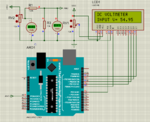
Above is the Arduino Circuit which i used to Simulate the original Arduino Version of the project. Below is the Arduino Code:
Below is the Circuit of the 16F886 Version. Though the Arduino is just to display the Dc Voltage Value but in the 18F886, I displayed some Characters that are STATIC and then the Variable values have their positions inside them as you can see in the picture/circuit:

16F886 code:
The Files are zipped/RAR including Simulation Schematic and 3-wire library:
As a learner, I have been doing whatever I could, to Learn Embedded programming.
I just started with LCD experiments what i saw in LCDs scared me initially. I later became little settled the time I started to see characters I desired appear on them and where I want them.
Behold! I thought that writing characters are just the same until I wanted to display sensor readings. for days I am hooked in some places...no escape, really!
Below, I will attach everything concerning this project/experiment.
It is about DC Voltmeter; 0-55VDC.
I first sow this project in Arduino and I simulated it with Proteus and actual hardware and it is working perfectly.
Because I am working with PIC Microcontrollers, I tried Port it and incorporate the code to an 16F886 Project I was experimenting on CCS C which I use,but it fail to display the. All the Static characters I earlier displayed on the 20x04 LCD are still displaying at their specified locations without distortion. Still, the DC value could not display anything anywhere on the LCD. Though I have not actually understand Strings and their rules.
Please cau people here do something for for this DC value to display at its position. I promise after this, i will add it to my non-volatile memory.

Above is the Arduino Circuit which i used to Simulate the original Arduino Version of the project. Below is the Arduino Code:
Code:
*/
#include <LiquidCrystal.h>
LiquidCrystal lcd(7, 8, 9, 10, 11, 12);
int analogInput = 0;
float vout = 0.0;
float vin = 0.0;
float R1 = 100000.0; // resistance of R1 (100K) -see text!
float R2 = 10000.0; // resistance of R2 (10K) - see text!
int value = 0;
void setup(){
   pinMode(analogInput, INPUT);
   lcd.begin(16, 2);
   lcd.print("DC VOLTMETER");
}
void loop(){
   // read the value at analog input
   value = analogRead(analogInput);
   vout = (value * 5.0) / 1024.0; // see text
   vin = vout / (R2/(R1+R2));
   if (vin<0.09) {
   vin=0.0;//statement to quash undesired reading !
}
lcd.setCursor(0, 1);
lcd.print("INPUT V= ");
lcd.print(vin);
delay(500);
}
Below is the Circuit of the 16F886 Version. Though the Arduino is just to display the Dc Voltage Value but in the 18F886, I displayed some Characters that are STATIC and then the Variable values have their positions inside them as you can see in the picture/circuit:

16F886 code:
Code:
//PIC16F886 with 3-wire LCD Experiments with CCS C Ver. 4.140


//LCD module connections
#define LCD_DATA_PIN PIN_B0
#define LCD_CLOCK_PIN PIN_B1
#define LCD_EN_PIN PIN_B2
//End LCD module connections

#include <16F886.h>
#device ADC = 10
#fuses HS,NOWDT,NOMCLR,NOPROTECT,NOLVP
#use delay(clock = 8000000)
#include <3WireLCD.c>


int value = 0;
int16 BV;
float vin = 0.0;
float vout= 0.0;
float R1 = 100000.0;             // 100k
float R2 = 10000.0;              // 10k


void main()

{
  lcd_initialize();                      // Initialize LCD module

  lcd_cmd(LCD_CLEAR);                       // Clear the LCD

//***********************************  FIRST ROW ************************
  lcd_goto(1, 1);                              // Go to column 3 row 1
  printf(lcd_out, "MY FIRST LCD PROJECT");   //These are Static on the LCD

 //*********************************  SECOND ROW ***********************
  lcd_goto(1, 2);                              // Go to column 4 row 2
  printf(lcd_out, "INPUT:  (   V)(  Hz)");   //These are Static on the LCD

//********************************  THIRD ROW ****************************
  lcd_goto(1, 3);                              // Go to column 4 row 3
  printf(lcd_out, "OUTPUT: (   V)(  Hz)"); //These are Static on the LCD

 //******************************** FOURTH ROW ***************************
  lcd_goto(1, 4);                              // Go to column 4 row 4
  printf(lcd_out, "BATTERY:        VDC");  //These are Static on the LCD
  delay_ms(200);

  setup_adc(ADC_CLOCK_DIV_8);            // 8Tosc ADC conversion time
  setup_comparator(NC_NC_NC_NC);         // disable comparator module
  delay_ms(10);
  setup_adc_ports( sAN0);                // Select Analog Inputs
  set_adc_channel(0);                     //Select AN0 as ADC Input for BV
  delay_ms(1);                            //Wait 1 ms
  BV = read_adc();                        //Read AN0 and stor in BV
  delay_ms(1);                            //Wait 1 ms

  vout = (value* 5.0)/1024.0;
  vin = vout/(R2/(R1+R2));
  if (vin<0.09)
  {
  vin=0.0;                       //statement to kill undesired reading !
  }
  {
  lcd_goto(10,4);
  printf(lcd_out,"%s",vin);      // I want the Vin to display its value here
  delay_ms(10);
}


  while(TRUE)
{
 }
}
The Files are zipped/RAR including Simulation Schematic and 3-wire library:


