Continue to Site

Welcome to EDAboard.com

Welcome to our site! EDAboard.com is an international Electronics Discussion Forum focused on EDA software, circuits, schematics, books, theory, papers, asic, pld, 8051, DSP, Network, RF, Analog Design, PCB, Service Manuals... and a whole lot more! To participate you need to register. Registration is free. Click here to register now.

help with mini Tesla coil!!

Status
Not open for further replies.

weaver

Newbie level 4
Newbie level 4
Joined
May 2, 2017
Messages
6
Helped
0
Reputation
0
Reaction score
0
Trophy points
1
Activity points
49
i recently got interested in making a mini tesla coil and things have not been gong so well.I found some online references on how to make them, so i followed them and can not manage to produce any ac voltage. I am getting .5 volts on dc at the top of my coil, which is what my resistor is putting off. I used a mje3055 transistor, a 22k ohm resistor 26 and 14 gauge wire for the coils. i just cant find out why the circuit is not functioning. Any help would be appreciated. IMG_0266.jpg
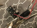
- - - Updated - - -

Sorry about the pics here's the one I was trying for IMG_0265.jpg
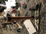
 

I suspect a fundemantal misunderstanding of how they work!

The primary of the coil has to be driven with AC but you picture shows no AC signal source. It will not work on DC alone.

I can't see it clearly in the picture but if there are three windings, with one connected to the base of the transistor (please show a schematic) which would imply it is self-oscillating, try reversing the wires on the feedback winding (the one wired to the transistor base pin but NOT both windings). If it does have a feedback winding, the phase of the feedback signal is critical and if wired backwards it actively tries not to oscillate!

Note that you probably need a much larger current source than those batteries can provide and the transistor will need to be mounted on a heat sink to keep it cool.

Brian.
 

Thanks for the reply. I have tried switching the wire on the base pin and with the one going to power and that didn't help. My transistor is getting warm but it's not like its overheating. Also I tested how many amps it is pulling out of the 12 volt battery back and it was only about .5, shouldn't that pack be able to do at least 1.5 amps. And here is the scmatic I have it wired by, minus the led. IMG_0267.PNG
 

That schematic is nonsense and will not work even if the LED, which is probably needed, is wired in. It has no realistic feedback path to make it oscillate and the transistor it mentions is far too small to work properly. Don't trust everything you see on the Internet, a lot of it is incorrect or only works by chance.

Connect the bottom of the existing 275 turn coil to the negative line.
Add another coil, try 3 turns but it may need more, at the bottom end of the 275 turn coil, near to the existing 33 turn coil. Wire one end to the base of the transistor, the other end to the junction of the 22K resistor and the LED. Wire the LED the other way around so the cathode goes to the negative line. Try it, if it doesn't work, swap the ends of the new coil over.

Brian.
 

Ok thanks. I just ordered some leds and a breadboard. I'll let post my results when they get here.
 

Ok so I got a breadboard and some leds and have been doing some testing. So I've got my bottom end of my 1200 turns of small diameter wire going to the base of my transistor. And I have one end of my 7 turn of larger wire going to the positive rail and the other end going to my emitter. On the collector pin I have my negative from the battery and positive end of my led. With the negotiate end connected to the base. And the resistor from my positive rail also connected to the base. I have tried 4, 9 and 12 volts and changed up the smaller coil from 3 to 10 turn with no results. I've also doubled my transistors with no luck. They are getting warm but not hot to the touch. Sorry for the long write up, hopefully someone can help me out.
 

There was no mention of a 1200 turn coil before but regardless, you didn't do as I suggested.

You should have THREE coils. The one with many turns is the high voltage output, connect the bottom end of it to the negative line.
Connect the emitter of the transistor to the negative line.
Connect the collector of the transistor through the 3 turn coil (I would use maybe 8 to 10 turns) to the positive line.
Connect the base of the transistor through the third coil (try 3 turns but it may need a few more) then to the 22K resistor.
The other end of the 22K resistor goes to the positive line.
If you want to add the LED, with it's anode (+) end to the junction of the coil and 22K resistor and the cathode (-) end to the negative line.

Keep the two small coils close to each other and at the bottom end of the big coil. If it doesn't work, swap the ends of the coil between the transistor base and resistor/LED over. Only swap the wires of one of the coils, it is the relative directions that matter so if you swap them both it negates the effect.

Brian.
 

Basically you need to setup an astable 555 circuit and have its output pin (3) drive the base of your transistor with a square wave.
And you will need to vary the frequency and duty cycle of your astable 555 until you find the optimal values for your particular coil.
Although it is unlikely to produce visible streamers. It will produce enough RF to excite a fluorescent tube though.

If you really want to get into Tesla coils then have a look here:
http://4hv.org/e107_plugins/forum/forum.php
http://www.stevehv.4hv.org/SSTC5.htm
**broken link removed**
 

Warning: Be VERY VERY careful if you build Steve Ward's design. The high voltage may burn you but it's pretty obvious it's there. The real danger lies in the low voltage side which as no isolation from the incoming AC from your wall socket and will be lethal if touched.

Brian.
 

Warning: Be VERY VERY careful if you build Steve Ward's design. The high voltage may burn you but it's pretty obvious it's there. The real danger lies in the low voltage side which as no isolation from the incoming AC from your wall socket and will be lethal if touched.

Brian.
He doesn't necessarily have to power it with 120VDC though. It works just as well with 12V from an ATX power supply even if it wont create visible streamers.
And the GDT gives the low voltage circuit some isolation from the high voltage part of the circuit anyway.

And if he got one of those 24VAC to 36VAC christmas light transformers and rectified it he would get 32VDC to 50VDC.

That would probably produce some small streamers and that sort of voltage level is relatively safe wouldn't you say Brian?
 

That all depends on how closely the original design is followed. It's true that reducing the supply voltage will also reduce the HV output but please bear in mind, and no disrespect is intended to Weaver here, he had trouble recognizing the mistakes in the first design then wired it differently than advised on the second attempt. Explaining how to connect and enable an ATX supply or rewire a wall-wart would make things far more complicated than necessary. I also worry with the Steve Ward design that the middle stage is 'floating' at line AC voltages, connecting any part of it to the output coil or the driver stage would be extremely dangerous and probably blow the house fuses.

For now, I suggest the self-oscillating single transistor idea is followed and maybe afterwards look at more efficient and reliable ways to improve it.

Brian.
 

Thanks for all the replys. I have tried your 3 coil design betwixt, but have had no results, I have tried switching the ends one at a time and trying different turn of each coil. Then I found a new video and schematic from https://www.electroboom.com/?p=521. I have followed his design except with a mje3055 transistor and led instead of diode. I am getting .7 volts D.C. Into my secondary coil, and my led glows, I'm not sure if that means if my transistor is stuck low or another problem.
 

I am getting .7 volts D.C. Into my secondary coil

To get that voltage it suggests the oscillator isn't running and all you are measuring is the B-E voltage of the transistor. To be honest, the original and electroboom designs are flawed and rely on uncontrollable factors such as stray capacitance. If you built ten of them they would all work differently. there is an additional problem with returning the high voltage winding to the transistor base pin that a sudden increase in load would likely kill it.

Please show how you built the design I suggested earlier, it should work and it should be reliable, if it didn't oscillate it suggests there wasn't enough coupling between the two low voltage windings. A picture would probably explain the problem.

Brian.
 

Status
Not open for further replies.

Part and Inventory Search

Welcome to EDABoard.com

Sponsor

Back
Top