tanhong007
Newbie level 4
I am looking for resources (books + papers) on inverting buck converter. But I can't find any over the internet or in the library. If you guys have any info about it, please let me know. Thank you very much!
Follow along with the video below to see how to install our site as a web app on your home screen.
Note: This feature may not be available in some browsers.
Did you mean it output a negative voltage?
https://www.engr.colostate.edu/ECE562/EE562_newlabs/Buck_Boost_OrCAD.pdf
No. It is like a regular buck converter, but move the inductor from the top to the button. I found one paper about that is from the IEEE, "Improving Current Regulation for Offline LED Driver". The author actually using an inverting-buck converter as an regular buck converter.
top to the bottom of what ? the PCB ? ;-) that didnt really make sense
the term "inverting buck converter" is as leo suggested for producing a negative voltage from a positive supply often needed for FET gate biasing
Dave
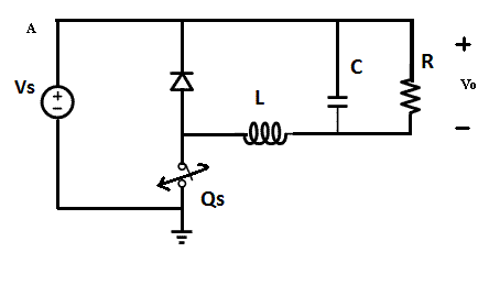
I modified your schematic:
The common voltage node will be node "A". The principle is similar to Buck.
If voltage on the diode is neglected, following equation will describe the output voltage:
Vo=D*Vs
Yes. The principle is very similar to Buck. I try to figure out what kind of advantage this topology has? And why people use this instead of Buck? When I use PSpice to do the simulation, I don't know how to do the closed loop, because I don't know how to make the model for the controller. Do you have any suggestion for this? Thank you very much for your help!
If you want to build AC model, it depends on the controlling model (voltage mode or current mode). The feedback voltage should be referenced to the supply voltage.
Right, I've used this type of buck when the load doesn't need to be ground referenced, like when driving LEDs or TECs. Having a ground referenced gate drive signal is pretty convenient.