Help with analyze a simple analog cirucit
- Thread starter eladta
- Start date
- Status
- Not open for further replies.


godfreyl
Advanced Member level 5

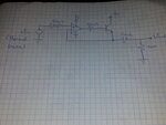
The voltage at the non-inverting input of the opamp = Vin. (The 200Ω resistor makes no difference).
The opamp drives the transistor to set the voltage at it's emitter = Vin.
The 100Ω and 20K resistors at the output form a voltahe divider, so Vout = Vin * (20000/20100) with no load, and the output impedance = 20K||100Ω.
The opamp drives the transistor to set the voltage at it's emitter = Vin.
The 100Ω and 20K resistors at the output form a voltahe divider, so Vout = Vin * (20000/20100) with no load, and the output impedance = 20K||100Ω.
godfreyl
Advanced Member level 5
If Vin = zero, then Vout = zero too, so bjt is off.
Also, if you connect a resistor between Vout and +Vcc, that can switch the bjt off, and Vout won't be able to follow Vin anymore.
Otherwise, yes, it's a simple buffer.
Also, if you connect a resistor between Vout and +Vcc, that can switch the bjt off, and Vout won't be able to follow Vin anymore.
Otherwise, yes, it's a simple buffer.
godfreyl
Advanced Member level 5
I don't know, maybe to get higher output current?so why do we need the bjt for ?
It's the parallel combination of the resistor from the emitter to Vout and the resistor from Vout to ground. Maybe I made a mistake, I thought they were 100Ω and 20K, now it looks like 200Ω and 20K.another question, how did u calculated the output impedance ?
eladta
Newbie level 5
It's the parallel combination of the resistor from the emitter to Vout and the resistor from Vout to ground. Maybe I made a mistake, I thought they were 100Ω and 20K, now it looks like 200Ω and 20K.
but they are not parallel connected, they are in series (the values are 20k and 100Ω)
godfreyl
Advanced Member level 5
Yes, but they are both connected to Vout, so any external load will see both of them as if they were in parallelbut they are not parallel connected, they are in series
If Vin is kept constant and a load resistor is added between Vout and ground, the output voltage will change and the current through both resistors will change. The current through the load will equal (change in current through 100Ω resistor) + (change in current through 20K resistor)
You sure? The first digit looks exactly the same.(the values are 20k and 100Ω)
eladta
Newbie level 5
Yes, but they are both connected to Vout, so any external load will see both of them as if they were in parallel
The basic definition for parallel conection is that EACH leg of the resistor will be connected to the other. In here they are only connected through Vout. the second wire of each resistor is connected to another point.
crutschow
Advanced Member level 6
- Joined
- Feb 22, 2012
- Messages
- 4,572
- Helped
- 1,006
- Reputation
- 2,010
- Reaction score
- 1,162
- Trophy points
- 1,393
- Location
- Colorado USA Zulu -7
- Activity points
- 26,054
The assumption here is that the output impedance of the transistor emitter is essentially zero due to the negative feedback. Thus, from a Thevenin view-point, the two resistors are in parallel to ground.The basic definition for parallel conection is that EACH leg of the resistor will be connected to the other. In here they are only connected through Vout. the second wire of each resistor is connected to another point.
eladta
Newbie level 5
The assumption here is that the output impedance of the transistor emitter is essentially zero due to the negative feedback. Thus, from a Thevenin view-point, the two resistors are in parallel to ground.
According this assumption you are right, but how can you justify that assumption ?
crutschow
Advanced Member level 6
- Joined
- Feb 22, 2012
- Messages
- 4,572
- Helped
- 1,006
- Reputation
- 2,010
- Reaction score
- 1,162
- Trophy points
- 1,393
- Location
- Colorado USA Zulu -7
- Activity points
- 26,054
Because the output impedance of the circuit is approximately the open loop output impedance of the emitter follower divided by the loop gain of the feedback loop. Given the high open-loop gain of a typical op amp, the calculated value for the output impedance will likely be a small fraction of an ohm.According this assumption you are right, but how can you justify that assumption ?
The calculation of this is left as a exercise to the reader. ;-)
- Status
- Not open for further replies.
Similar threads
-
Help with circuit analysis of an old analog SS amp
- Started by Vokzel
- Replies: 2
-
-
-
-