AbhimanyuSingh
Member level 1

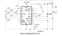
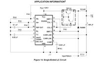
This is one of the test circuits given in datasheet of SG3524, with a little modification, mostly insignificant, like changing the value of inductor and using just one BJT instead of 2, as given in datasheet. I am not getting any output there. The expected % volts is not there. The signal out of pin 13 has a duty ratio of almost 0. What could the reason be. What possible mistake have I made. Even if I change the voltage at pin 2 (off course remove this voltage divider and put a rheostat), I dont find any change in duty ratio.
Also once it happened, in another occasion that I was getting 2 volts at that point once I switched on the circuit and that voltage remained there even after i switched off the power supply. What could be a reason for this.
The circuit is built on a bread-board. So its a little lousy, but there were no loose-wires.
I am posting the circuit diagrams. The first file is the circuit i have built and the second file is the test circuit given in datasheet of Texas Instruments.


