Continue to Site

Help needed to analyse the circuit

Status
Not open for further replies.

Zohra_malik

Newbie level 5
Newbie level 5
Joined
Nov 6, 2012
Messages
10
Helped
0
Reputation
0
Reaction score
0
Trophy points
1,281
Activity points
1,360
Dear All,

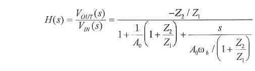
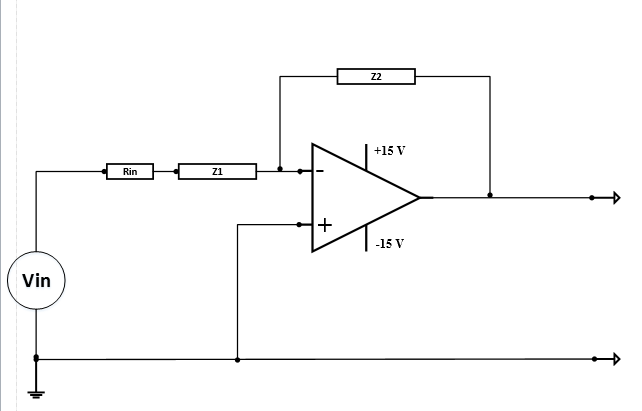
I want to write a transfer function in S-Domain by considering the limitation of operational amplifier gain and bandwidth. The circuit is attached. Your help is appreciated.

5152394800_1383075680.png


Regards
Zohra
 

Zohra,
start with the classical feedback model (for a fixed opamp gain A) and - as a second step - insert A=-Ao/(1+s/wo) .
Then, rearrange the resulting expression with the aim to get a polynominal in "s" in the denominator.
 
Last edited:

Zohra,
start with the classical feedback model (for a fixed opamp gain A) and - as a second step - insert A=-Ao/(1+s/wo) .
The, rearrange the resulting expression with the aim to get a polynominal in "s" in the denominator.
Hi LVW

Thanks a lot for your reply. Could you please tell me what do you mean by classical feedback model. One thing come in my mind
which is Vout=(Z2/Z1)*Vin. Would you please suggest me is that right way to think?

- - - Updated - - -

Would you please also let me know any existing general equation for this type of circuit in the form of H(s).

5764093200_1383084745.png


I have this general equation but I really can't understand.
 

You can start from the classical feedback from the system control theory:


α is the input divider coefficient, that is α=Z2/(Rin+Z1+Z2)
β is the feedback coefficient, that is β=(Rin+Z1)/(Rin+Z1+Z2)

if "x" is the input node of the amplifier, then:

x=α•Vin-β•Vout
Vout=-F(s)•x

from which:

Vout/Vin=-α•F(s)/[1+β•F(s)]

Using now the expressions for α and β:

Vout/Vin=-Z2•F(s)/[Rin+Z1+Z2+(Rin+Z1)•F(s)]

Now if you model the op amp as a first order system, having DC gain Ao and pole ωp, then:

F(s)=Ao/(1+s/ωp), then:

Vout/Vin=[-Z2*Ao/(1+s/ωp)]/[Rin+Z1+Z2+Z1•Ao/(1+s/ωp)]

Dividing now, both numerator and denominator, by Z1•Ao/(1+s/ωp) and rearranging you will obtain the equation you post.
 
Last edited:

You can start from the classical feedback from the system control theory:


α is the input divider coefficient, that is α=Z2/(Rin+Z1+Z2)
β is the feedback coefficient, that is β=(Rin+Z1)/(Rin+Z1+Z2)

if "x" is the input node of the amplifier, then:

x=α•Vin-β•Vout
Vout=-F(s)•x

from which:

Vout/Vin=-α•F(s)/[1+β•F(s)]

Using now the expressions for α and β:

Vout/Vin=-Z2•F(s)/[Rin+Z1+Z2+(Rin+Z1)•F(s)]

Now if you model the op amp as a first order system, having DC gain Ao and pole ωp, then:

F(s)=Ao/(1+s/ωp), then:

Vout/Vin=[-Z2*Ao/(1+s/ωp)]/[Rin+Z1+Z2+Z1•Ao/(1+s/ωp)]

Dividing now, both numerator and denominator, by Z1•Ao/(1+s/ωp) and rearranging you will obtain the equation you post.


Hi albbg,

Thanks very much for explaining me the equation. I was really struggling with this equation. Now would you please tell me how to calculate the open loop gain of the op amp. Also I have installed a first order high pass filter at the end of Vout to stop low frequency drift in the range of 0.3Hz. I want to analyze the circuit in term of frequency response. I want to plot Bode plot for this circuit.

Kind Regards,
Zohra
 

Zohra, just for your information:
At the begining of albbg`s excellent answer you see a feedback model using "alpha" and "beta". This model is called "classical feedback model".
 

Status
Not open for further replies.

Part and Inventory Search

Welcome to EDABoard.com

Sponsor

Back
Top