Continue to Site

Welcome to EDAboard.com

Welcome to our site! EDAboard.com is an international Electronics Discussion Forum focused on EDA software, circuits, schematics, books, theory, papers, asic, pld, 8051, DSP, Network, RF, Analog Design, PCB, Service Manuals... and a whole lot more! To participate you need to register. Registration is free. Click here to register now.

Help needed in circuit analysis

Status
Not open for further replies.

Zohra_malik

Newbie level 5
Newbie level 5
Joined
Nov 6, 2012
Messages
10
Helped
0
Reputation
0
Reaction score
0
Trophy points
1,281
Activity points
1,360
Dear all,

I am configuring the integrator and circuit diagram is attached. I don't have a background in electronic and I am just building circuit for my project. I am asking to expert to take have a look and help me to analyse the circuit and indicate any mistake. Additionally, I have another issue with gain of signal. Gain in this case C1/C2 but for some reason I am not able to see the gain practically. Any little help will do a job.

Kind Regards,
Zohra Malik

- - - Updated - - -

Here is attached circuit diagram:
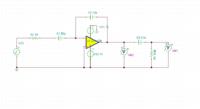
 

You have no DC bias point for the inverting input. Add a high value resistor to somewhere, such as GND.

Keith
 

Remove C1 in case you want to realize an (inverting) integrator.
More than that, the dimensioning of the time constant R2*C2=1E6*1E-11=1E-5 sec is VERY far from an optimum design.
Why not R2=1E4 and C2=1E-9 ?
 

You have no DC bias point for the inverting input. Add a high value resistor to somewhere, such as GND.

Keith

Would you please elaborate it more.

- - - Updated - - -

C2 working as a sensitivity capacitor, lower the value of the capacitor better the sensitivity can be achieved.
 

The inverting input of the opamp must have a DC path to somewhere otherwise it will just float around and the difference between that and the non-inverting input will be amplified by the open loop gain and the opamp output will end up at one supply rail or the other.

As LvW said, if you want an integrator, remove C1. That will also give you a DC path to the inverting input.

Keith.
 

Help needed to analyse the circuit.

Dear all,

Anybody help me to analyze the circuit. I am using it for my project and I need somebody help me to understand it.

Many thanks,


Re: Help needed to analyse the circuit.

Dear all,

Anybody help me to analyze the circuit. I am using it for my project and I need somebody help me to understand it.

Many thanks,
Hi Zohra
May i ask you a question :
Why your circuit has no DC feedback ? and also inverting input has no DC bias ?
 

Re: Help needed to analyse the circuit.

Please say what do you want to do with the circuit. Because as it is, it seems incomplete. You may want to move the thread from microntrollers to a more suitable section to get more help.
 

As has already been said - there is no DC bias for the opamp inverting input. Even a CMOS opamp needs the inputs connecting to somewhere from a DC point of view otherwise they will just drift out of the common mode voltage range of the opamp and it will not work.

As albert says - you need to say what you want it to do. As it stand it is useless and wouldn't do anything. Even if you add a 10M resistor to ground from the inverting input it still wouldn't be terribly useful. With different values (and a DC path to ground [or somewhere else]) it could be a charge amplifier. C1 could be meant to represent the source capacitance of a sensor which requires a charge amplifier - who knows?

Keith
 

Re: Help needed to analyse the circuit.

Please say what do you want to do with the circuit. Because as it is, it seems incomplete. You may want to move the thread from microntrollers to a more suitable section to get more help.

Albert, did I understand you right? We shall say what we "want to do with the circuit"?
Perhaps we should ask you what your application is.
Did you understand the comment from Keith (post#5) and the question from Goldsmith (post#7)?
The circuit cannot work as it is - but what`s your goal?
 

The first post says the gain should be C1/C2 implying a charge amplifier. See attached.

Keith
 

Attachments

  • Perfect charge amplifier 1.pdf
    5.1 KB · Views: 95

Re: Help needed to analyse the circuit.

Dear goldsmith,
Actually I am trying to use circuit as pure integrator. This is the main reason to not to use dc gain.

- - - Updated - - -

Dear Keith, Lvw and albert22 I am thankful to you. Actually I am using this configuration of circuit to connect it to the sensor. In this case the integrating capacitor used as sensitivity capacitor.
 

Dear goldsmith,
Actually I am trying to use circuit as pure integrator. This is the main reason to not to use dc gain.
Well , another question : do you know what i mean by DC feedback and what is the advantage of a DC feedback in an integrator ?
Pure integration ? why not a usual Miller integrator ?
Best Wishes
Goldsmith
 

Re: Help needed to analyse the circuit.

Thanks LvW, I read the post#3, actually I am using this circuit as a amplifying the output from the sensor and integrating it. The input of the circuit is i=dq/dt I want to integrate this output from the sensor and present it in the form of voltage output. V=1/c(int(i)).
Nose C1 I am using as decoupling capacitor to stop any dc component of the signal and let the ac signal pass and send it to the integrator. Hopefully you will explain my point. I am really appreciating help from all of you guys.

Many thanks

- - - Updated - - -

Dear Goldsmith, would you please explaing the Dc feedback.
 

I am using as decoupling capacitor to stop any dc component of the signal and let the ac signal pass and send it to the integrator.

Please somebody correct me if I am wrong. If you completely block DC and then integrate. I think that the output will be zero.
Then I dont understand why you want to block DC. Can you be more specific about the sensor? Datasheet?
Plase forgive me if I am asking too many questions.

LvW
Albert, did I understand you right? We shall say what we "want to do with the circuit"?
Perhaps we should ask you what your application is.

When I replied to this post it was marked as "unanswered" probably my fault was not refreshing my browser while I was typing. My aim was to help and luckily, for me, zohra got my point.
 

When I replied to this post it was marked as "unanswered" probably my fault was not refreshing my browser while I was typing. My aim was to help and luckily, for me, zohra got my point.

Oh, I`m sorry, albert. At the moment of writing I was of the opinion that YOU was the originator of the thread. Please, forgive me.

- - - Updated - - -

...........................
Nose C1 I am using as decoupling capacitor to stop any dc component of the signal and let the ac signal pass and send it to the integrator.

But unfortunately this capacitor blocks also the dc bias current, which is needed by each opamp.

Why don`t you inform you about working integrator circuits before blindly starting into such experiments (Internet, textbooks)?
 

Sorry Lvw I didn't just close my eyes and start building the circuit. Practically I am achieving the good results. I just need to explain it theoretically. I am not able to explain very clearly perhaps. See the attached image, in this image you can see the input and output response.

Oh, I`m sorry, albert. At the moment of writing I was of the opinion that YOU was the originator of the thread. Please, forgive me.

- - - Updated - - -


But unfortunately this capacitor blocks also the dc bias current, which is needed by each opamp.

Why don`t you inform you about working integrator circuits before blindly starting into such experiments (Internet, textbooks)?
 

Sorry Lvw I didn't just close my eyes and start building the circuit. Practically I am achieving the good results. I just need to explain it theoretically. I am not able to explain very clearly perhaps. See the attached image, in this image you can see the input and output response.


Results achieved in practice or with a simulation program? If simulation - real or ideal opamp model? With the circuit as shown in post#6 ?
 

In practice means practically. The bandwidth of the signal achieved as I was expecting. Even in simulation I am getting the good results by using real opamp model with the circuit shown in post#6.
Results achieved in practice or with a simulation program? If simulation - real or ideal opamp model? With the circuit as shown in post#6 ?
 

Status
Not open for further replies.

Part and Inventory Search

Welcome to EDABoard.com

Sponsor

Back
Top