You take the advice already given about the basic parts you need.
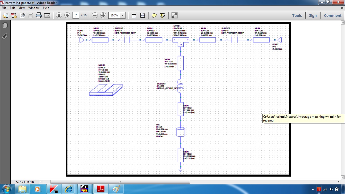
Then, you make the circuit again, using microstrip parts to include a short piece of line at the input up to the capacitor which is likely 50 Ohm. You place a MSUB element, and fill in the values concerning the substrate, like thickness and Er.
If the capacitor needs a footprint pad, place that, along with any step width change bits that are consequential.
Then, a length of strip up to the stub that is going to do the job of the inductor. You might possibly make it hang off the capacitor pad, but life is easier if all the lengths between lumped-components parts are not expected to be zero!
A MTEE part, or a MTEE$ if you want the "intelligent type that automatically inherits the widths of whatever it gets connected to. This connects your stub that replaces the inductor
There may be a need for more - like a thin high-inductance track arriving for bias, maybe even via a wound inductor and decoupling capacitor. Instead of direct shorting the end if the stub, you might use sideways placed capacitors to do the "shorting", so that you can sneak the DC bias up the stub instead of using another MTEE$ to get the bias onto the gate. You end up with a whole long chain of stuff in your schematic, both on input and output.
Then you simulate using the S-parameter model for your active device, paying attention to stability factor, and noise figure. Invoke the "tune" feature, and tweak or optimize to bring the physical design closer to your lumped-element target. You may find you revise some features of your design.
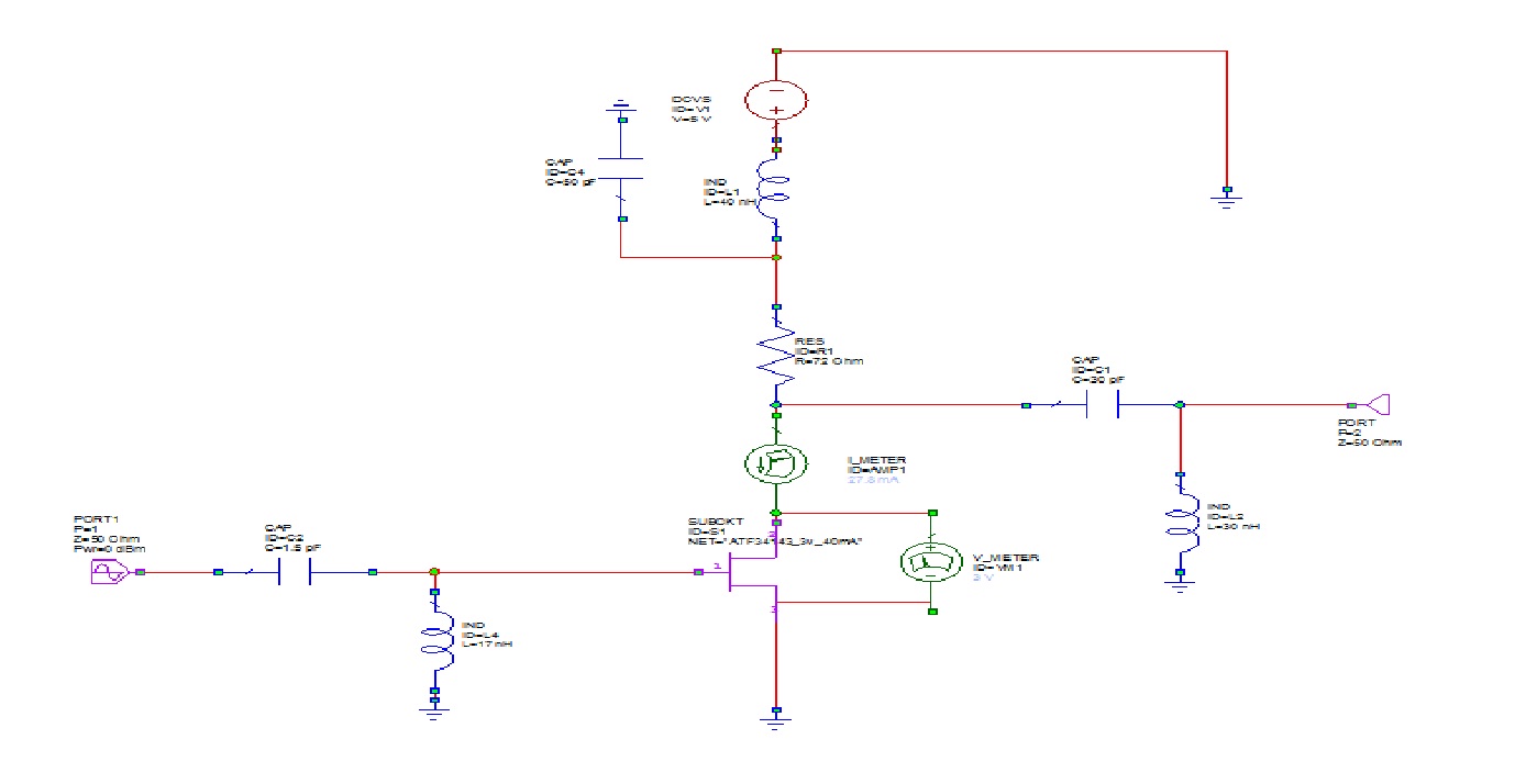
Consider feeding DC to the drain via at a inductor that has high impedance at 1.3GHz. If there has to be a resistor, it goes the other side of the inductor, and has a decoupling capacitor between. In a low-noise amplifier, you try and avoid coupling in noise from resistors. It is less serious on drain than on gate circuits , but if you want it good then at least put the resistors behind inductors.
One hopes the design is stable, meaning stable at frequencies way outside of the band you are interested in. ATF34143 still has substantial gain up to 6Ghz, and really very high gains below 1GHz, like at UHF, HF, and even DC. It could oscillate violently at audio frequencies. You may need some deliberate inductance in the source, and other feedback compromise tricks, to get it stable. The bad constraint here is how to do it without too much noise from resistors.