Continue to Site

Welcome to EDAboard.com

Welcome to our site! EDAboard.com is an international Electronics Discussion Forum focused on EDA software, circuits, schematics, books, theory, papers, asic, pld, 8051, DSP, Network, RF, Analog Design, PCB, Service Manuals... and a whole lot more! To participate you need to register. Registration is free. Click here to register now.

Help me repair an Oscilloscope: Phillips PM3260e

Status
Not open for further replies.

ignas

Newbie level 4
Newbie level 4
Joined
Aug 21, 2008
Messages
6
Helped
0
Reputation
0
Reaction score
0
Trophy points
1,281
Activity points
1,332
I bough a used, nonworking oscilloscope Phillips PM3260e in attempt to fix it.

The symptom: there is no trace. Only when powering down it shows a disappearing beam on the CRT. (Maybe a leaky capacitor?)

First I checked the PSU, found few faulty capacitors with my ESR meter, replaced them. Now PSU seems fine, all voltages are correct.
But there's still no trace. After much trial and error, I narrowed it down to the DC restorer or the blanking circuit.

PM3260E_CRT_schematic.jpg

If I quickly short the cathode and the first grid of CRT (between GR522 and GR523 diodes) for an instant , I see a very bright trace and it looks OK.

I have no experience with CRT's, so how to isolate the problem even further?

Appreciate any help!
 
Last edited:

You should check the intensity control path.

TS511/512 are acting as a multivibrator, generating a square wave variable by the intensity potentiometer. It's coupled to cathode potential by C521 and rectified by GR511/512. Check if the circuit is working and generates a variable voltage across R564.

A too large voltage drop across stabilizer glow-discharge lamps B501/502 (might be exhausted) could be problem, too.
 
  • Like
Reactions: ignas

    ignas

    Points: 2
    Helpful Answer Positive Rating
That part of the circuit looks partly potted around a plastic case over it. I will have to pry it open somehow, hopefully it's not fully potted.

Thank you for the step in the right direction, highly appreciate it!
 

Check the signal at the deflection yoke. Horizontal and vertical. Also the beam intensity circuit.

I bough a used, nonworking oscilloscope Phillips PM3260e in attempt to fix it.

The symptom: there is no trace. Only when powering down it shows a disappearing beam on the CRT. (Maybe a leaky capacitor?)

First I checked the PSU, found few faulty capacitors with my ESR meter, replaced them. Now PSU seems fine, all voltages are correct.
But there's still no trace. After much trial and error, I narrowed it down to the DC restorer or the blanking circuit.

View attachment 91768

If I quickly short the cathode and the first grid of CRT (between GR522 and GR523 diodes) for an instant , I see a very bright trace and it looks OK.

I have no experience with CRT's, so how to isolate the problem even further?

Appreciate any help!
 
  • Like
Reactions: ignas

    ignas

    Points: 2
    Helpful Answer Positive Rating
Check the signal at the deflection yoke. Horizontal and vertical.
Horizontal and vertical deflection seems to be OK, the horizontal voltages vary and vertical is at 20V (which is mentioned correct in the Service Manual).

Check if the circuit is working and generates a variable voltage across R564.
Unfortunately, I can't measure the voltage across the R564 as I turn R547 yet. But it doesn't change the control grid voltage, when I turn it the voltage jumps a little and then stabilizes.

I measured the voltage between the cathode and the first (control) grid, as I turn the Intensity pot (R20) on the front of the panel, it changes from -163V to -122V, is the grid voltage too negative?
 

I measured the voltage between the cathode and the first (control) grid, as I turn the Intensity pot (R20) on the front of the panel, it changes from -163V to -122V, is the grid voltage too negative?
So you verified that the intensity control is basically working. My hand calculation of the circuit tells that the negative grid voltage should be -120 V maximum. You might check by shorting it with a high ohmic resitor for test. The voltage might be too high if e.g. the ZA 1004 tubes are exhausted, as said.
 
  • Like
Reactions: ignas

    ignas

    Points: 2
    Helpful Answer Positive Rating
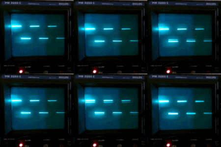
Tried to connect a 1MΩ between cathode and grid and it works, the grid voltage is -45V when looking at 2khz calibration signal:

scope.gif [Animated image] The waveform wobbles (maybe a PSU ripple), but everything works fine.
The wave seems to fade out, is it normal?

Measured the -2kV output and it's -2.2kV. I changed the regulator feedback divider (removed R2005) and made it exactly -2kV, but it didn't solve the problem. Should I keep it as it was?

What else could cause the grid voltage to get so high?
Should I try to open the sealed/potted board with the ZA1004 and replace them?
 

I'm not sure. Can you measure the voltage between -2kV node and CRT cathode?
 
  • Like
Reactions: ignas

    ignas

    Points: 2
    Helpful Answer Positive Rating
I adjusted the grid bias R547 with 1MΩ between cathode and grid and made the fading from left to right disappear, as well as changing the minimum intensity point on the front panel.

Can you measure the voltage between -2kV node and CRT cathode?
Measured 413V. Is it too high? (The ZA1004 have an ignition voltage of 90V and extinction of 80V)
 

Measured 413V. Is it too high? (The ZA1004 have an ignition voltage of 90V and extinction of 80V)
Most likely. The current through the 10 k resistor should be expected below 1 mA, so the voltage drop is obviously at the Z1004 tubes.
 
  • Like
Reactions: ignas

    ignas

    Points: 2
    Helpful Answer Positive Rating
So the exhausted neon bulbs causes the control grid voltage to be too high, is that correct?

What should I do?
  • Try to open the sealed/potted board and replace the ZA1004? But the manual states:
    potted.jpg It's probably fully potted, so nearly impossible.
  • Build a duplicate board from schematic (inside a dashed line) using new parts?
However, would the resistor between cathode and grid be a viable solution? Could this damage something or lower the life of CRT tube?

Or there's another way to lower the grid voltage? Add a zener for sufficient voltage drop?
 

Status
Not open for further replies.

Similar threads

Part and Inventory Search

Welcome to EDABoard.com

Sponsor

Back
Top