Continue to Site

Help in designing a Flyback with MC34063

NikoTico

Newbie
Newbie level 4
Joined
Mar 24, 2025
Messages
5
Helped
0
Reputation
0
Reaction score
0
Trophy points
1
Activity points
63
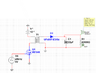
I am designing a flyback source using the MC34063 IC with the goal of raising the voltage from 12V to 500V and providing an output current of 10mA. My idea is that the output is adjustable by means of a potentiometer, modifying the feedback voltage. This power supply is intended to power small tube amplifiers and to refurbish condensers.

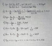
For the design, I used the formulas provided by Electgpl, but when performing a simulation in Multisim, I get about 70V of output instead of the expected 500V. I would like someone with experience in sources of this topology to help me verify if the calculations I made are correct and, if not, guide me on how to correct them.

[Initial post in foreign language:
Estoy diseñando una fuente flyback utilizando el IC MC34063 con el objetivo de elevar la tensión de 12V a 500V y proporcionar una corriente de salida de 10mA. Mi idea es que la salida sea regulable mediante un potenciómetro, modificando la tensión de retroalimentación (feedback). Esta fuente está destinada a alimentar pequeños amplificadores valvulares y a reformar condensores.

Para el diseño, utilicé las fórmulas proporcionadas por Electgpl, pero al realizar una simulación en Multisim, obtengo aproximadamente 70V de salida en lugar de los 500V esperados. Me gustaría que alguien con experiencia en fuentes de esta topología me ayudara a verificar si los cálculos que realicé son correctos y, en caso contrario, me orientara sobre cómo corregirlos.]
 

Attachments

  • Captura de pantalla 2025-03-28 215522.png
    Captura de pantalla 2025-03-28 215522.png
    23.6 KB · Views: 32
  • WhatsApp Image 2025-03-28 at 9.44.05 PM.jpeg
    WhatsApp Image 2025-03-28 at 9.44.05 PM.jpeg
    266.7 KB · Views: 37
Last edited by a moderator:
There are better suited controllers for flyback with MOSFET switcher like MC3842. MC34063 has hysteresic control rather than stable PWM, but it can be used. Essential to connect Ipk sense to high side of primary winding. Gate drive must use pull-down resistor, you may want to add diode + pnp to speed up switch-off without using very low resistor value.
 
Hello, in that sense I agree with you, the 3842 has an advantage over the 34063, but I couldn't get it, at least at a reasonable price. Also to speed up the shutdown I was planning to use a 1K resistor with a 2N3906, as a diode will a 1N4148 do?

[Moderator action: translation]
 
Last edited by a moderator:
why not cascaded boost...surely you dont need isolation because your 12v is surely isolated?
Use eg ucc28c43 and use external error amplifier so you can adjust output volts....if you want i send LTspice?
 
Simple flyback converter. Notice transformer primary conducts during one half of cycle. Secondary conducts during other half of cycle. (To accomplish this the secondary connection should resemble dots on windings as below.)

Snubbing network included.
12V supply does not necessarily share same ground with 500V output.
1.5M resistor was added to discourage rogue oscillations in simulator.
flyback 40kHz 12V to 500V load 10mA (with snubbing).png

--- Updated ---

Link below runs above schematic in Falstad's animated interactive simulator:

tinyurl.com/28oc7v85
 
Recientemente abrí la simulación en LTSpice. Aunque conozco el programa, no estoy completamente familiarizado con él. Modifiqué los valores de inductancia que había calculado previamente y obtuve las tensiones que se muestran en la imagen. No vi la necesidad de reemplazar los componentes por los que tengo (IRF640 y UF4007). En principio, diseña la placa y ensambla el circuito.

Solo tengo dos dudas:

¿Querría añadir un amortiguador en serie con un diodo o dejarlo como está en la simulación?

¿Qué define la frecuencia de oscilación del MC34064? Entiendo que es el condensador CT (C1), pero no encontré por ningún lado el cálculo que establece esa frecuencia en esta configuración. ; traducirlo al inglés

[Translation by Google:]

I recently opened the simulation on LTSpice. Although I know the show, I'm not fully familiar with it. I modified the inductance values I had previously calculated and got the stresses shown in the image. I didn't see the need to replace the components I have (IRF640 and UF4007). In principle, design the plate and assemble the circuit.

I have only two doubts:

Would you like to add a serial shock absorber with a diode or leave it as it is in the simulation?

What defines the oscillation frequency of MC34064? I understand it's the CT (C1) capacitor, but I didn't find anywhere the calculation that sets that frequency in this configuration. . .


1743358992946.png
 
Last edited by a moderator:
I was using MOSFET and rectifier diodes available for simulation, I have no specific suggestions in this regard. However, you are reducing winding ratio N2:N1 = 6.5 (L2:L1 = 41.7), not corresponding to your calculation in post #1. I guess it's a calculation error, confusing winding and inductance ratio.

I'm under the impression that primary and secondary snubber are necessary to keep transistor and diode voltage ratings.

Regarding Ct dimensioning, I'd refer to AN920-D https://www.onsemi.com/pub/collateral/an920-d.pdf


Write your reply...

LaTeX Commands Quick-Menu:

Similar threads

Part and Inventory Search

Welcome to EDABoard.com

Sponsor

Back
Top