Continue to Site

Welcome to EDAboard.com

Welcome to our site! EDAboard.com is an international Electronics Discussion Forum focused on EDA software, circuits, schematics, books, theory, papers, asic, pld, 8051, DSP, Network, RF, Analog Design, PCB, Service Manuals... and a whole lot more! To participate you need to register. Registration is free. Click here to register now.

HELP - distorted current flowing through a toroidal inductor

Status
Not open for further replies.

powersys

Advanced Member level 1
Joined
Nov 29, 2005
Messages
439
Helped
3
Reputation
6
Reaction score
2
Trophy points
1,298
Activity points
4,981
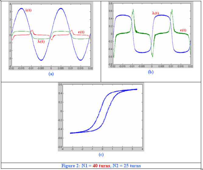
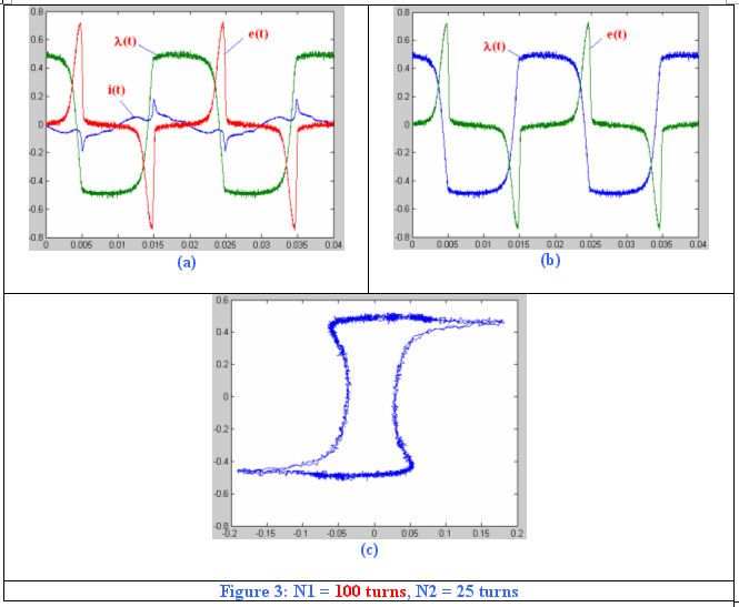
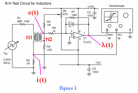
I did a test on a BH circuit (Figure 1) today. The number of turn of the excitation coil was N1, whilst the number of turn of the search coil was N2. In the experiment TTi TG550 Function Generator (https://www.tti-test.com/products-tti/generator/tg550.htm) was used as Vin. When N1 = 100 turns, the excitation current waveform looked very FUNNY (heavily distorted compared to that when N1 = 40 turns). I'm not sure what's the cause of the distortion. Is it because of the TG550 (low output current capacility), or because of the 'reactance' of the circuit itself?

I also connected the BH circuit to an AC power supply (capable of supplying up to 8A, 0~24Vrms), and the excitation current waveform was also distorted heavily. Due to the heavily distorted current waveform, the BH curve also looked weird.

Please advise...

Thank you very much
17_1187801838.jpg


15_1187801871.jpg


89_1187801916.jpg
 

Re: HELP - distorted current flowing through a toroidal indu

Your disorted waveforms are caused by fenomenon called 'saturation'. The greater N, the lower current saturates your core. You should learn about basic terms and depedencies in magnetical circuits and think it over. Afterwards when you compare your waveforms to those in books you'll get all your answers.
I know that experimenting is much more interesting than learning theory, but without elementary theoretical knowledge about magnetic circuit you won't understand many things... (or even nothing at all)
Above all, exactly the same problem was discussed about six..seven months ago, so read the archive!

mateuko
 

    powersys

    Points: 2
    Helpful Answer Positive Rating
Re: HELP - distorted current flowing through a toroidal indu

mateuko said:
Your disorted waveforms are caused by fenomenon called 'saturation'. The greater N, the lower current saturates your core. You should learn about basic terms and depedencies in magnetical circuits and think it over. Afterwards when you compare your waveforms to those in books you'll get all your answers.
I know that experimenting is much more interesting than learning theory, but without elementary theoretical knowledge about magnetic circuit you won't understand many things... (or even nothing at all)
Above all, exactly the same problem was discussed about six..seven months ago, so read the archive!
Thanks for your reply. I was the one who initiated the thread that discussed the same problem about six months ago. You may refer the thread here:

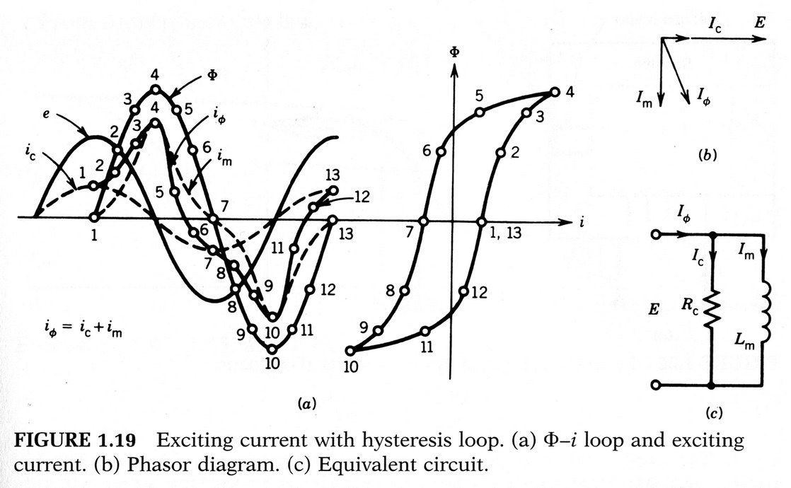
I did some reading on magnetic circuit especially those described in Sen's textbook (see figure below) but I still could not understand. Let's refer to measured i(t) when N1 = 100 turns. At every cycle, the excitation current waveform increased slowly initially, then dropped slightly, afterward increased sharply, then dropped sharply before it decreased slowly. Do you think the measured i(t) matches those showed in Sen's textbook as given in figure below?

Besides, when I added an 1kohm resistor in series with the excitation circuit (when N1 = 100 turns), the excitation current waveform i(t) became sinuisoidal again. I recall your comments in previous post:

The current is sill sinusoidal because at 50Hz the reactance of your primary coil have very minor impact on the primary circuit impedance. Try this experiment at 20...100kHz and the current will not be sinusoidal any longer. The circuit with OP amp is useless at such frequencies... Use higher oscilloscope amplification instead.
Do you know any circuit simulation software that has such 'inductor' model?

29_1173630432.jpg
 

Status
Not open for further replies.

Similar threads

Part and Inventory Search

Welcome to EDABoard.com

Sponsor

Back
Top