Salvador12
Full Member level 4

So I have the following problem, there is a ventilator using BLDC motor 3 phase which is drive by electronics on a single board, IC's and fets etc.
There is a speed control circuit not directly connected to the main board but instead "talking" to the board via optoisolators.
This board as a +10volt output pin, and then it has ground pin and A+ and B- pins for what I understand to be a variable speed control input via low voltage.
The problem is in this low voltage input circuit someone added a too high voltage and the input protection diodes are blown out.
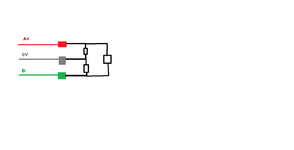
I have attached a schematic of how those diodes are connected but they are SMD type and some "noname" brand so there are no real readable markings or any other signs just a small black package.
Can you please help me figure out the polarity based on how they are arranged in the circuit, overall there are 3 diode.
Please see attached picture.

