Continue to Site

Welcome to EDAboard.com

Welcome to our site! EDAboard.com is an international Electronics Discussion Forum focused on EDA software, circuits, schematics, books, theory, papers, asic, pld, 8051, DSP, Network, RF, Analog Design, PCB, Service Manuals... and a whole lot more! To participate you need to register. Registration is free. Click here to register now.

Help calculate voltage steps and time duration of 1/4 of sine wave.

Status
Not open for further replies.

ALERTLINKS

Advanced Member level 4
Joined
Dec 13, 2003
Messages
1,258
Helped
396
Reputation
786
Reaction score
380
Trophy points
1,363
Location
Pakistan
Activity points
7,263
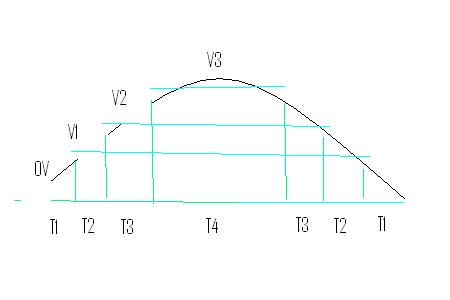
I want to build a 220v 50Hz inverter with three or voltage four steps for 1/4 of sine wave. I need to calculate the best combination of voltages and the interval between them for optimum performance and low distortion. there will be three or four dc voltage sources(as required) including one for maximum around 300 volts.At first it will be stepped from low, medium to high then to medium to low and then to 0v for half cycle of sine wave.
60_1316923350.jpg


I need values for time, T1, T2, T3,T4 and voltages V1, V2 and V3 for best performance.
 
Last edited:

Sine wave general function is y = sin(x) * A || A=Amplitude
One function cycle is 0..360 degrees or 0...2*PI radians

in picture V = sin(T) * Vp || Vp= Voltage peak value

Picture shows half cycle ( 0...180 degrees) (0...PI radians)

Now you can calculate every point in function of sine ( x-axis in degrees or radians )

Degrees to time :
if sine wave frequency is f , then time for 360 degrees is 1/f = time of one cycle
in case radians >>> time for 2*PI radians is 1/f

Example:
frequency is 50Hz
Vp= 220V * 2^0.5 = 220V * (square root(2)) = 311V
f= 1/50 [sec] = 0.02 sec = 20ms this time is for 360 degrees (or 2*PI radians)

so find voltage in point x = 35 degrees
y = 311V * sin(35) = 178.4V
and time is 20ms * 35/360 = 1.944 ms

or find voltage in 3ms
x = 3/20 * 360 = 54 degrees
so y = 311V * sin(54) = 251.6V

or where is voltage 200V
value of sin(x) is (200/311) = 0.6431
and x = arcsin(0.6431) >>> 40.02 degrees
and time in 40.02degrees is 40.02/360 * 20ms = 2.22ms

In short.............

y= A * sin(xAngle) >>> [degrees]

xAngle= time(x)/time(360) >>> [degrees]

y/A = sin(xAngle) = sin( time(x) / time(360)) >>> [degrees]

y = sin(xAngle) / A = sin( time(x) / time(360)) / A >>> [degrees]

time(x) = time(360) * arcsin (y/A) / 360 >>> [degrees]

in case radians..............................................................

y= A * sin(xAngle) >>> [rads]

xAngle= time(x)/time(2*PI) >>> [rads]

y/A = sin(xAngle) = sin( time(x) / time(2*PI)) >>> [rads]

y = sin(xAngle) / A = sin( time(x) / time(2*PI)) / A >>> [rads]

time(x) = time(2*PI) * arcsin (y/A) / 2*PI >>> [rads]


Hope you got idea................
 
Last edited:
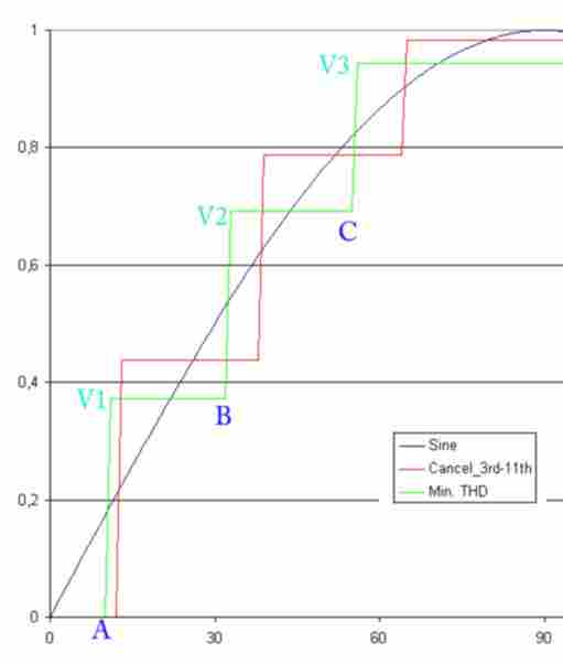
The term "best performance" would need clarification first. Depending on the kind of load connected to the inverter, different criteria come into play. If you go for low distortion, you should be able to setup a three level inverter for cancellation for 3rd to 9th harmonics. Just calculate the fourier series of the step voltage sum and optimize the parameters. You have 4 free parameters besides fundamental magnitude.
 

To continue the previous considerations, there are actually 5 free parameters for a 3-level inverter, so cancellation of 3rd to 11th harmonics is possible. Alternatively you can minimize total THD which leads to a different optimization. The total THD is only slightly improved, 9.3 % compared to 11.4 % for the harmonic cancellation case.


P.S.: The calculation is using the fourier series discussed in this post https://www.edaboard.com/threads/149378/#post640154
 

Attachments

  • 3-level-sine.zip
    25.7 KB · Views: 62
Last edited:
so find voltage in point x = 35 degrees
y = 311V * sin(35) = 178.4V
and time is 20ms * 35/360 = 1.944 ms
If i make equel intervals and manage voltage of three diferent values according to 15,45 and 75 degrees for 1/4 wave three level inverter. That was basic idea to go forward. But i found that distortion level and power output can be improved by adjusting degrees and voltages for the same three levels. And third harmonic is better for inductive loads.It is filtered out automatically and power is increased.
cancellation of 3rd to 11th harmonics is possible. Alternatively you can minimize total THD which leads to a different optimization.
The load is home appliances including fans, computer, energy savers and kitchen machines.
More common inverters are sqare wave and step sine wave. So what i should look for to further improve although pure sine wave inverter using pwm is an option. It seems to me that three step inverter can handle more power using low speed power
switching devices( which are cheap). For optimising between better power output and distortion, how should i tweak
swithing time and voltages for improved efficiency for this load. Is this consideration important and what other factors i should also consider?
 
Last edited:

It's clear, that selected harmonics can be cancelled or the total THD can be minimized, if both magnitude and pulse width of superimposed pulses are adjusted. Another question is, if you have suitable hardware means to generate steps of arbitrary magnitude. Multi-level inverters are known concept in high power electronics, but it's usually involving equal step magnitudes.
 

Multi-level inverters are known concept in high power electronics, but it's usually involving equal step magnitudes.
I found these systems in use for long time.It was easy to generate equel timing steps then. Now its easy to adjust timing using microcontroller or it is used because it does not make much difference for practical purposes? Voltages will be generated using tapping in same transformer after recification and filtering for three positive and three negative values. I am considering simple three steps not superimposing pwm pulses as this will complicate things. Will it out perform step sine wave(1/3t off,1/3t on,1/3t off). I think i follow graph with green line. Can you give me exact values for degrees and voltages to impliment.
13_1316985115.jpg
 
Last edited:

Status
Not open for further replies.

Part and Inventory Search

Welcome to EDABoard.com

Sponsor

Back
Top