Continue to Site

Welcome to EDAboard.com

Welcome to our site! EDAboard.com is an international Electronics Discussion Forum focused on EDA software, circuits, schematics, books, theory, papers, asic, pld, 8051, DSP, Network, RF, Analog Design, PCB, Service Manuals... and a whole lot more! To participate you need to register. Registration is free. Click here to register now.

Heat sink for MOSFET

Status
Not open for further replies.

AgnesAnna

Newbie level 6
Newbie level 6
Joined
Oct 22, 2016
Messages
12
Helped
0
Reputation
0
Reaction score
0
Trophy points
1
Activity points
119
Hi all,

I would like to know whether it is compulsory to use heat sink for MOSFET or boost diode in PFC circuit. I have used UC3854 IC for switching the MOSFET in the boost converter. A 20 ohm resistor was connected in series to the gate. 17 V Vcc was given to UC3854 IC. Is there any additional protection circuit needed? The rating of MOSFET is 800V , 17A. Input to boost converter is around 325V dc.
 

Hi,

Heatsink..

You will find the information in the datasheet.
The higher the power dissipation, the higher the temperature rise.
The lower the thermal resistance junction to ambient, the lower the temperature rise.
(Unfortunately your given data say nothing about power dissipation, and nothing about thermal resistance)

You need to ensure that the junction temperature is below it's specified limit.
But usually one doesn't go to this limit.

Klaus
 
The answer about expectable boost switcher power dissipation is not in the MOSFET datasheet, at least not as such. It depends in a first order on load power and switching frequency. Having these data you can estimate rise and fall times and respectively switching losses together with conduction losses. Then decide about heat sink.

In practice, small boost converters up to a few 10 W may get away without a transistor heat sink.
 
**broken link removed**

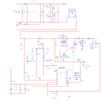
Here i have attached the schematics of the circuit developed. While doing hardware, at the gate of mosfet , a 20 ohm resistor was connected. Also, the secondary terminal of inductor connections which are used to give Vcc to UC3854 was removed and an external dc supply of 17V was used. But even for an input voltage of 30 V , the mosfet blasted. On further investigation it was observed that the bridge rectifier at the input side also damaged. What could be the possible reasons? The current sense resistor used in the ground return path was normal 0.1 ohm diode. Is there any special sense resistor for this purpose?

Ratings are:
Vin:230V
Vout=420Vdc
Pout=540W
fs=100kHz(mosfet)
 

Well did you use the correct power diode, because if not then boost fet in pfc will die from high reverse recovery current....you need a siC diode or Qspeed diode. Infineon.com have some great app notes for you on PFC FETs and diodes and circuits etc
 
I used a schottky SiC diode- STPSC1206D(600V,12A ).I didnt use a snubber circuit nor heat sink. Can it be the reason? Is there any other possible reason??

MOSFET used is SPW17N80C3(800V,17A).
 

Post #4 has invalid attachment, please reload the schematic.
 

Post #4 has invalid attachment, please reload the schematic.

SCHEMATICS.png

Sorry for that....I hope it's ok now...
 

Please put a heat sink first.

Are you driving at full load, if yes then input current will be around 20A that will be causing the trouble.
 
Status
Not open for further replies.

Similar threads

Part and Inventory Search

Welcome to EDABoard.com

Sponsor

Back
Top