Continue to Site

Welcome to EDAboard.com

Welcome to our site! EDAboard.com is an international Electronics Discussion Forum focused on EDA software, circuits, schematics, books, theory, papers, asic, pld, 8051, DSP, Network, RF, Analog Design, PCB, Service Manuals... and a whole lot more! To participate you need to register. Registration is free. Click here to register now.

[SOLVED] Heart beat monitoring system using pic16f877a

Status
Not open for further replies.

aswathymohan

Member level 4
Member level 4
Joined
Nov 11, 2012
Messages
68
Helped
5
Reputation
10
Reaction score
5
Trophy points
1,288
Activity points
1,727
Hi

Pl post the mikroc code for the calculation of heart beat monitoring system using pic16f877a..I have seen a thread here..I just copied and did the same thing where i may confused with the calculation of heart beat per min.pl help...


Code:
// LCD module connections
sbit LCD_RS at RB0_bit;
sbit LCD_EN at RB1_bit;
sbit LCD_D4 at RB2_bit;
sbit LCD_D5 at RB3_bit;
sbit LCD_D6 at RB4_bit;
sbit LCD_D7 at RB5_bit;
sbit LCD_RS_Direction at TRISB0_bit;
sbit LCD_EN_Direction at TRISB1_bit;
sbit LCD_D4_Direction at TRISB2_bit;
sbit LCD_D5_Direction at TRISB3_bit;
sbit LCD_D6_Direction at TRISB4_bit;
sbit LCD_D7_Direction at TRISB5_bit;
// End LCD module connections

unsigned inputsignal=0;
unsigned int firstRun = 1;
unsigned int cnt=0; // Define variable cnt == 1KHz clk
long HR=0;
char *text;
unsigned char outlcd;
 char uart_rd;
 char uart_rd1[15];
 
 void call();
void interrupt() {
cnt++; // Interrupt causes cnt to be incremented by 1
TMR0 = 194; // Timer TMR0 is returned its initial value
INTCON = 0x20; // Bit T0IE is set, bit T0IF is cleared
}

void main()
 {


OPTION_REG = 0x84; // Prescaler is assigned to timer TMR0
ADCON0=0X81; // Pins AN1 is configured as analog
TRISA = 0xFF; // All port A pins are configured as inputs
ADCON1=0X00;
//TRISC = 0; // All port C pins are configured as outputs
TRISD = 0; // All port D pins are configured as outputs
//PORTC = 0x00; // Reset port C
PORTD = 0x00; // Reset port D
UART1_Init(9600);
   delay_ms(100);

//ADCON1.F4 = 0 ; // VSS voltage reference
//ADCON1.F7 = 1 ; //A/D Conversion Result Format Select bit adfm=1
//ADCON0 = 0x07; // A/D is enabled and AN1 is analog input
Lcd_Init(); // LCD display initialization
Lcd_Cmd(_LCD_CURSOR_OFF); // LCD command (cursor off)
Lcd_Cmd(_LCD_CLEAR); // LCD command (clear LCD)

text = "WELCOME...... "; // Define the first message
Lcd_Cmd(_LCD_CLEAR);
Lcd_Out(1,2,text); // Write the first message in the first line
text ="HEART BEAT METER";
Lcd_Out(2,1,text);
delay_ms(100);
delay_ms(100);
delay_ms(100);
delay_ms(100);
delay_ms(100);


while(1)
 {

                   inputsignal = ADC_Read(1);
                   if (inputsignal>=64)
                   {
                      delay_ms(50);
                      if (firstRun==1)
                      {
                         firstRun = 0;
                         cnt = 0; // Variable cnt is assigned a 0
                         TMR0 = 194; // Timer T0 counts from 194 to 255
                         INTCON = 0xA0; // Enable interrupt TMR0
                      }
                   else
                   {
//find heart rate
                         Lcd_Cmd(_LCD_CLEAR);
                         text="Heart rate=";
                         Lcd_Out(1,1,text);
//number of interrupt is time between two pulses in ms
                         HR=60000/cnt;
                         outlcd=HR/100 ; //hundreds digit in HR
                         Lcd_Chr(1,12,48+outlcd); // Write result in ASCII format
                         outlcd=(HR/100)%10;//tens digit in HR
                         Lcd_Chr_CP(48+outlcd);
                         outlcd=(HR)%10 ;//ones digit in HR
                         Lcd_Chr_CP(48+outlcd);
                         Lcd_out(2,5,"puls/min.");

//Lcd_Cmd(_LCD_CLEAR);
//rest vlaue of counter
//and start next test    

                         cnt = 0 ;
                         TMR0 = 194; // Timer T0 counts from 194 to 255
                         INTCON = 0xA0; // Enable interrupt TMR0

                 
            }
        }
     }
 }
 

Re: Heart beat monitoring stem using pic16f877a

:020000001e29b7
:100006002428c03083120313f0004e28f930f00084
:100016004e28a430f0004e28b030f0004e2899301b
:10002600f0004e289230f0004e288230f0004e2824
:10003600f830f0004e288030f0004e289030f00066
:100046004e28831203132a08003a031904282a08a3
:10005600013a031909282a08023a03190c282a0822
:10006600033a03190f282a08043a031912282a0802
:10007600053a031915282a08063a031918282a08e2
:10008600073a03191b282a08083a03191e282a08c2
:08009600093a031921280800b2
:0e009e008312031321088a0020088200080044
:1000ac0083120313f8010830fc00700df80d74086e
:1000bc00f80203186328f8070310f00dfc0b5b28fb
:0200cc0008002a
:1000ce00831203137008f100f0010830fc00710870
:1000de00f40c03187628fc0b6f28f1010034031082
:1000ee007b28f40c0318f107f10cf00cfc0b7828ac
:0200fe000800f8
:10010000073083120313fc007d30fd00fd0b8628b1
:06011000fc0b862808002c
:10011600023083120313fb008630fc009930fd0089
:0e012600fd0b9328fc0b9328fb0b932808007d
:100134008312031385158b208b2081014d30fb0026
:100144001930fc004f30fd00fd0ba628fc0ba6283f
:10015400fb0ba6280000000085110108a600260854
:0c016400a500a50d2510a50d2510080014
:100170000a3083120313f4002508f0005620780893
:10018000f0007008a9007008aa000320831203136e
:100190007008a9000a30f4002508f00056200a3043
:1001a000f40056207808f0007008a8007008aa0033
:1001b0000320831203137008a8006430f40025089c
:1001c000f00056207008a7007008aa0003208312d0
:1001d00003137008a700a301a401b430f0002208a3
:1001e000f400672024087102031df8282308700218
:1001f000031c102905118514051429088600802088
:10020000051585100514280886008020051585141d
:100210000510270886008020a30a0319a40aed28e8
:0402200005140800b9
:100224004f208a110a128000840aa00a0319a10a25
:08023400f003031d122908006c
:10023c000730831203139f00303083168500803003
:10024c008600283081008312a5010130a200b8205d
:10025c00861b35298b209a200330a200b8202e292a
:02026c00362931
:02400e006a2125
:00000001ff
 

Re: Heart beat monitoring stem using pic16f877a

Show us your pseudo code and HW schematic, indicate the problem areas
 
Re: Heart beat monitoring stem using pic16f877a

I have to do a heart beat measuring device with laser-ldr. And I am good on pic16f877a can you share the diagram of your project ?
Or any idea how to do it ?
 

Re: Heart beat monitoring stem using pic16f877a

Capture2.PNGOfcourse ....I did it with ldr ..Working and setup is simple to understand..Ldr detects the photonic signals,those signals amplified and given to pic as square pulses.I have used LM358N.Pic do the processing part..it counts the no of pulses in every 1 ms using timer 0 interrupt.those count will be converted and will be equivalent to bpm..Hope this helps..
 
Last edited:
Re: Heart beat monitoring stem using pic16f877a

Use this projects, code is in MikroC for PIC16F628A, you can easily adjust for PIC16F877A:

Firmware source is made in MikroC and you can adjust time for counting.

Heart rate measurement from fingertip
https://embedded-lab.com/blog/?p=1671

Code:
/*
  Project: Measuring heart rate through fingertip
  Copyright @ Rajendra Bhatt
  January 18, 2011
  PIC16F628A at 4.0 MHz external clock, MCLR enabled
*/

sbit IR_Tx at RA3_bit;
sbit DD0_Set at RA2_bit;
sbit DD1_Set at RA1_bit;
sbit DD2_Set at RA0_bit;
sbit start at RB7_bit;
unsigned short j, DD0, DD1, DD2, DD3;
unsigned short pulserate, pulsecount;
unsigned int i;
//-------------- Function to Return mask for common anode 7-seg. display
unsigned short mask(unsigned short num) {
 switch (num) {
 case 0 : return 0xC0;
 case 1 : return 0xF9;
 case 2 : return 0xA4;
 case 3 : return 0xB0;
 case 4 : return 0x99;
 case 5 : return 0x92;
 case 6 : return 0x82;
 case 7 : return 0xF8;
 case 8 : return 0x80;
 case 9 : return 0x90;
 } //case end
}

void delay_debounce(){
 Delay_ms(300);
}

void delay_refresh(){
 Delay_ms(5);
}

void countpulse(){
 IR_Tx = 1;
 delay_debounce();
 delay_debounce();
 TMR0=0;
 Delay_ms(15000);  // Delay 1 Sec
 IR_Tx = 0;
 pulsecount = TMR0;
 pulserate = pulsecount*4;
}

void display(){
  DD0 = pulserate%10;
  DD0 = mask(DD0);
  DD1 = (pulserate/10)%10;
  DD1 = mask(DD1);
  DD2 = pulserate/100;
  DD2 = mask(DD2);
  for (i = 0; i<=180*j; i++) {
    DD0_Set = 0;
    DD1_Set = 1;
    DD2_Set = 1;
    PORTB = DD0;
    delay_refresh();
    DD0_Set = 1;
    DD1_Set = 0;
    DD2_Set = 1;
    PORTB = DD1;
    delay_refresh();
    DD0_Set = 1;
    DD1_Set = 1;
    DD2_Set = 0;
    PORTB = DD2;
    delay_refresh();
    }
  DD2_Set = 1;
}

void main() {
 CMCON = 0x07;    // Disable Comparators
 TRISA = 0b00110000; // RA4/T0CKI input, RA5 is I/P only
 TRISB = 0b10000000; // RB7 input, rest output
 OPTION_REG = 0b00101000; // Prescaler (1:1), TOCS =1 for counter mode
 pulserate = 0;
 j = 1;
 display();
 do {
  if(!start){
   delay_debounce();
   countpulse();
   j= 3;
   display();
  }
 } while(1);  // Infinite loop
}


And for pulse sensing use this newer detecting circuit:

Introducing Easy Pulse: A DIY photoplethysmographic sensor for measuring heart rate
https://embedded-lab.com/blog/?p=5508

You can replace TCRT1000 with L-53P3C 5mm phototransistor and MCP6004 with LM324D, for TX led I use red 5mm high bright 15000mcd, and all works fine. All is in SMD and are very small.
 
Last edited:
  • Like
Reactions: tusemo

    tusemo

    Points: 2
    Helpful Answer Positive Rating
Re: Heart beat monitoring stem using pic16f877a

Thank you, may I use directly a laser as light source ?
And, LDR as signal receiver, lm358 to get square wave ?
and how should I count the pulses can you explain a little bit detail (Should I record the pulses in one minute )?
 

Re: Heart beat monitoring stem using pic16f877a

Thank you, may I use directly a laser as light source ?
And, LDR as signal receiver, lm358 to get square wave ?
and how should I count the pulses can you explain a little bit detail (Should I record the pulses in one minute )?

You dont have needs to use laser as light source, beleive me Red LED 5mm at UltraHell 15000mcd is enough to blind. uC in circuit switch off red led on idle, and turn on only when Start button is pressed. Led is turned on for 15 seconds. I use LM324 as I described. Circuit measure pulses in 15sec period, then count that value with 4 to get measurement in 60sec (1min). You can adjust that values in source code if you want to play on 10sec of measurement and multiple that value with 6 to get measurement in 60sec.


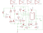
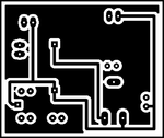
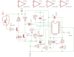
Circuit for detector:

HeartBeatPulseDetector.png

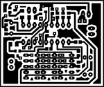
PCB_Bottom.png PCB_Top.png


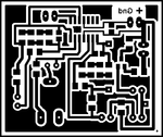
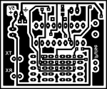
Circuit for counting:

HeartRateMeasurementCkt1.jpg

PCB Top.png PCB Bottom.png


IR TX (Pin2 on PIC16F628) connect to JP1 (Pin2).

Vout from LM324 connect to I/P Pulse (Pin3 PIC16F628).

Pay attention on uC type if PIC16F628A or PIC16F628, HEX is not the same, and problem will appear if you try to put 628A into 628 (led flickering, timer poblems, code protect option in PICKit2,...). If you have PIC16F628 just open source in MikroC, adjust project configuration to use PIC16F628 (not 628A), compile source to HEX, and thats it.

This two PCBs, pulse detecting and counting are adjusted to be linked as sandwich.

Firmware in attachment is adjusted to measuring in 15sec and give HBR (HBR/min) for 1min.
 

Attachments

  • 00.RAR
    1.5 KB · Views: 211
  • Parts.txt
    1 KB · Views: 191
Last edited:
  • Like
Reactions: tusemo

    tusemo

    Points: 2
    Helpful Answer Positive Rating
Re: Heart beat monitoring stem using pic16f877a

thank you so much, tpetar.
 

Re: Heart beat monitoring stem using pic16f877a

I will post photos of finished device PCB soon (I must connect external HD to PC and search files). :smile:
 

Re: Heart beat monitoring stem using pic16f877a

Ok, really thanks

- - - Updated - - -

Dear tpetar , my teacher gave this project (heart beat measuring) with laser instead of led. The all circuit is still valid ??
 

Re: Heart beat monitoring stem using pic16f877a

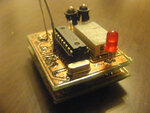
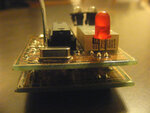
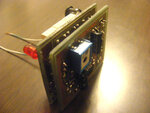
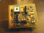
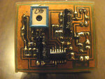
PCBs from post #10 should looks like this after linking together :

DSCF0236.JPG DSCF0237.JPG DSCF0239.JPG DSCF0308.JPG DSCF0310.JPG

I didnt have some parts in SMD near hand.

Device is very precize, and can be powered over 9V battery with small voltage regulator 78M05 and two tantal 10uF capacitors on input and output (small SMD PCB).

Dear tpetar , my teacher gave this project (heart beat measuring) with laser instead of led. The all circuit is still valid ??

Yes my friend, circuit and PCBs works 100%. You can experiment with different kind of light source even with laser, signal output also can be easily used in some other counting/logging circuit if needed.

Like I say in earlier post one PCB is sensing/detecting PCB with LM324, and other is counting with µC and showing result on 7-seg 3 digit display.

You can modify code to sens pulse in 5 seconds and multiply that value with 12, default is counting in 15 seconds then multiply with 4 to get result per minute (HBR/min).

;-)
 
Last edited:
  • Like
Reactions: tusemo

    tusemo

    Points: 2
    Helpful Answer Positive Rating
Re: Heart beat monitoring stem using pic16f877a

Thank for your help, but I dont understand the usage of the red circulated device, what is this device ? ,than you
HeartBeatPulseDetector.png

- - - Updated - - -
 
Last edited:

Re: Heart beat monitoring stem using pic16f877a

JP1 is jumper, when connected RED TX LED works always, and when JP1 Pin2 is connected to Pin2 of PIC16F628 in Post #10, then uC controls red led and turn on that led only during measurement.

In situation when you want to make and use only sensing/detecting circuit, you just short that jumper.
 
Last edited:

Can anyone provide the circuit for the above code
 

Status
Not open for further replies.

Similar threads

Part and Inventory Search

Welcome to EDABoard.com

Sponsor

Back
Top