Continue to Site

Welcome to EDAboard.com

Welcome to our site! EDAboard.com is an international Electronics Discussion Forum focused on EDA software, circuits, schematics, books, theory, papers, asic, pld, 8051, DSP, Network, RF, Analog Design, PCB, Service Manuals... and a whole lot more! To participate you need to register. Registration is free. Click here to register now.

Headphone amp, microphone trim

Status
Not open for further replies.

imdacrocker

Newbie level 6
Newbie level 6
Joined
Oct 13, 2012
Messages
11
Helped
0
Reputation
0
Reaction score
0
Trophy points
1,281
Activity points
1,406
Hi, I am relatively new with building my own PCB stuff, but have been moderately successful so far.

So here's my problem. I operate an endurance road race team, and we are low budget. Rather than have some fancy radios, we use our iPhones as communication between the driver and pit. It works well, but there are some complications.

We use an in helmet headset like this:

https://www.planetheadset.com/helmet-headset.php

But the problem is that it doesn't seem to be designed for high volume environments, like a noisy car traveling at 100 plus MPH. The iPhone is somewhat limited in its software capabilities.

The mic is positioned very close to the driver, but the wind noise and car noise seem to peak the capabilities of the iPhone, causing it to cut in and out. And the headset isn't QUITE loud enough for the track.

So I was looking into a headset amplifier. I ended up buying the MicroMon MA 400 (**broken link removed**) but it turns out it isn't a microphone or headphone amplifier, just a trim.

I found plans for a headphone amplifier (https://tangentsoft.net/audio/cmoy-tutorial/) which I feel confident I could build. But it presents two problems.

I need to be able to turn the microphone down. I don't need to amplify it any, just turn it down.

And I need to maintain my remote abilities. The push to talk button on the headset linked above is critical, as sometimes our call is lost. The driver needs to be able to pick up the phone (as iPhone doesn't have an auto-answer).

Any suggestions on a circuit that could do this?
 

It's "do-able" with some extra electronics but by the time you have made the microphone attenuator, headset amplifier and a push-to-talk (PTT) circuit you are most of the way to a new wireless link anyway. It may be more appropriate to drop the iPhone and just use short range radio modules.

I used to operate ham radio from a motorcyle so I appreciate the problems. My experience is that the headset volume isn't the issue, making it louder just makes the driver deaf, what you need to concentrate on is reducing the background noise level. I did lots of experimenting and there isn't an easy solution that doesn't also compromise the safety of the driver. Before looking at volume levels, try this simple experiment: Get a sheet of expanded polystyrene (styrofoam) and shape a thin cup that is barely thicker than the earphone. Set the earphone into it so it's rear (outside) is sealed to outside air. This will help to prevent sound passing straight through it but still allow sound produced inside it to reach the ears. Most helmets have sufficient "ear space" to allow you to do this and hopefully, the styrofoam will not make it unsafe in case of a collision.

Brian.
 

What all is involved with a microphone attenuator and a PTT circuit that makes it so difficult and/or expensive?

And I understand what you are getting at in regards to headphone placement. My helmet has a little space where the earpieces fit quite nicely. One of our other drivers had to hollow out their ear pad, and it places the earbud further from their ear. They have a harder time hearing.

While I think we need to move his headphones closer, mine work pretty decently. I just need them to be a few decibels louder to hear just a little better. I can get it most of the time, but not all of the time. Unfortunately, we are required to wear multi-layer balaclavas, which don't help.

And I'm not quite sure why, but my microphone seems to work fine, but others are overloading. Probably due to helmet design and mic placement.

A far as the PTT goes, the actual headset plugs into another wiring section that contains the PTT button and the headset plug. I could use this amplifier/attenuator before that junction, which may eliminate my need for a PTT circuit. I'm still curious how they work, and how I could keep that signal intact.

Our current solution is to put in a set of in-ear microphones, which allow the driver to hear pretty well. However, they are a pain to put in, and the in-ear bits start to hurt about an hour and a half into your stint. I also want something that is easier to take off, to keep things safer in the case of emergency. My system comes completely off with my hemet.
 

Interesting discovery today. Turns out the headset is Mono, and the remote runs directly to the right side input. So all I really need is to figure out how to make a mono variable microphone attenuator, I can figure out the headset amplifier.
 

The microphone attenuator needs be no more complicated thatn a simple potentiometer costing pennies. The problem will be making the iPhone still recognize it a a microphone afterwards. It will probably work fine but some phones, including mine look at the resistance across the input connections to decide what if anything is plugged in. For example on mine, a high resistance makes it think a microphones is plugged in (such as on a handsfree kit) but a low resistance changes the mic input into a video output. The solution is to use a potentiometer as a volume control on the microphone so you can set the level then use a buffer to maintain the impedance at the iPhone to keep that happy. Initially, try it without buffering, it may work for you. All you do is buy a potentiometer, it can be one like a volume control with a knob or a "pre-set" one which has a slot you adjust with a screwdriver depending on how frequently you think it may need adjustment. You have to break into the micophone cable, it will be a center wire with a shield around it. The shiield must be reconnected as it's very important that it still does it's job but the inner wire goes to the potentiometer. Connect the microphone side to one end of the potentiometer, the iPhone end to the wiper (center) pn and connect the other potentiometer end to the shields. Adjusting the potentiometer will let you set the mic level from zero to almost full level.

For the earphones, I wouldn't suggest using the cmoy design as it can easily become unstable with some designs of headphone. Yiou can make a simpler, cheaper and more suitable amplifier using a simple LM386 IC which is designed specifically for low level speaker and heaphone driving. It also only needs a single battery so is less bulky.

Brian.
 

So when I look up microphone attenuation circuits, I notice the basic circuit, like below, has a shunt to ground instead of just a resistor. Can I not do that in this case? If I can and want to do it this way, what resistor pot should I buy? It doesn't exactly give me a part number.

http://www.uneeda-audio.com/pads/
 

In principle yes, a "T" network will work but it doesn't have to be even that complicated. Two resistors will work, one in series with the microphone and one across the iPhone input. The values depend upon how much attenuation you need and to some extent on how tolerant the iPhone is of micrphone impedance. When using two resistors, increasing the value of the series resistor or reducing the shunt resistor will both reduce the level, that's why a potentiometer is the best component to use. As the control is adjusted, the resistance from the wiper increases from one end of the track as it reduces from the other so it gives you a continuously variable level out. Adjusting it for the optimal level would be far easier than trying to measure and calculate the microphone impedance, gain and the iPhone input requirements to calculate fixed resistor values. I would suggest starting with a 10K potentiometer and see if it works. There may still be problems with the iPhone input rejecting it anyway but for such low cost it's worth trying. Even if a buffer amplifier is needed, the potentiometer would still be necessary to adjust the levels.

Brian.
 

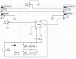
Ok, I am trying to build my circuit, and this is my first attempt.

I stole the virtual ground circuit from the CMOY circuit, though I don't fully understand it.

Also, most of the lm386 circuits are either 5v or 12v, and I plan on powering directly from the DC in the car, so do I need to add anything to regulate the power? There will be an alternator in there, I'm not sure what that does to things.

And different diagrams have different resistors shunting in different places, I'm not really sure what applies to my amplifier...

Screen Shot 2012-12-13 at 8.11.40 PM.png
 

I'm not sure that will work.
The virtual ground isn't necessary if you use an LM386 because it has it's own internal biasing circuits. In any case, there isn't a virtual ground in that circuit, I think you are confusing it with the mid-rail voltage at the junction of the two resistors. A virtual ground is a node in a circuit that has no signal on it and usually can sink signal current but isn't actually connected to real ground. You achieve it by combining the input signal with an inverted copy of itself so they cancel out. If you simply copy the basic design from the data sheet it should work and be simpler as well.
To be honest, the CMOY circuit isn't very good, it is only a low power op-amp circuit and it isn't designed to handle low impedance loads, especially inductive ones like headphones. It copes but it could be much better and I would guess it is just the result of someone experimenting rather than professional standard design.

Brian.
 

Redesigned.

I keep seeing different values for resistors and capacitors, not sure which ones to use..

Screen Shot 2012-12-14 at 7.33.00 AM.png
 

That looks fine except for two minor points:
1. I'm guessing the microphone is an electret type and it needs DC across it to work but with a 14V supply you might be pushing too much current through it when R3 is only 2.2K. You probably want about 1mA to flow so a value around 10K would be better.
2. At the moment, as you adjust the volume control you inject DC from it into the LM386 input. Add a capacitor of say 1uF (not critical) at the top end of the volume control to block the DC. The + end should be toward R3.

Try it out, if the volume is too low there is a simple modification to increase the gain but check it first, it may not be necessary and it has some adverse effects.

Brian.
 

Last edited:

Ok, so my little amp just got more complicated.

I want to build into it a feature for doing something like this:

**broken link removed**

So I need to split both the incoming audio and microphone signals, and combine them with an ambient noise microphone, and send that signal to the gopro that it can understand.

I have been reading about audio mixing, but I'm not sure exactly how to mix the signals that are coming and going, as well as combining a microphone line with a headphone line.

Suggestions?
 

I assume you mean as in the video - except it just shows as a white box here!

Sounds like you got the amplifier working anyway so "well done" for that.

I thnk you are asking for a three input mixer with sources of incming audio, microphone and ambient. It's quite easy to do, you need three level controls to adjust the relative volume of each source, an amplifier and I'm guessing an output splitter as well. Before going further, how do you resolve the power supply problem mentioned earlier? The type of power source has relevance to the design of mixer so it's best to know before making suggestions.

Brian.
 
Last edited:

Actually, I have not gotten the amp up and running yet. I have tried several different configurations based on circuits I found online, but I can't seem to get it to work. I haven't tried a regulator yet, my local radioshack was out. I plan on using a simple 7812 regulator, though. I'm not sure if I managed to blow my LM386, but I bought a couple of them. I just didn't want to plug in a new one until I get the voltage regulator in place, so I don't blow up another.

So if I understand correctly, I need to split both the headphone and microphone inputs, feed them into another amp along with the ambient microphone, as well as still use the headphone amp as above, and another amp for the microphone signal going to the iPhone?

While I'm at it, is there any sort of simple noise-cancelling circuit I could use between the ambient microphone and the headset microphone?
 

It's 10:30pm here and I just got back from a long meeting so I'm not going to start drawing schematics right now.

Can you draw a block diagram of exactly what you need for me. Nothing fancy, just a box for each sound source and each destination and where you want to control the levels, joined by arrows to show the signal paths.

Noise cancellation is possible but rarely gives very good results. It involves taking two sound samples from very close to each other, one facing the source and one avoiding it. The signals are then electrically subtracted so anything common to both is eliminated. If the microphones are too far apart the sound waves arriving will be shifted in phase because of the different distances they have travelled and in the worst case can add and make the background twice as loud as the sound you want! To work perfectly the microphones have to be identical and pick up exactly the same sounds from exactly the same position and of course that makes it impossible for one to hear and the other to avoid hearing the sound you want to keep. You can get a degree of cancellation but don't expect too much and it certainly wont work if one is mobile and the other fixed.

Brian.
 

Status
Not open for further replies.

Part and Inventory Search

Welcome to EDABoard.com

Sponsor

Back
Top