Continue to Site

Welcome to EDAboard.com

Welcome to our site! EDAboard.com is an international Electronics Discussion Forum focused on EDA software, circuits, schematics, books, theory, papers, asic, pld, 8051, DSP, Network, RF, Analog Design, PCB, Service Manuals... and a whole lot more! To participate you need to register. Registration is free. Click here to register now.

[SOLVED] Half-Bridge Motor Driver Oscillations

Status
Not open for further replies.

gbmhunter

Junior Member level 1
Joined
Apr 6, 2011
Messages
16
Helped
1
Reputation
2
Reaction score
1
Trophy points
1,283
Location
New Zealand
Activity points
1,419
Hi,

I am currently building a half-bridge motor driver for a 800W DC motor.

I am using the LM5104M half-bridge driver IC to drive the gates of two discrete N-Channel MOSFET's. The driver uses boot-strapping to provide the high-side gate driver.

When testing the circuit, I have noticed problematic oscillations occurring. They get worse as the current increases (e.g. 0.5A to 1A), and get worse as the PWM frequency increases (e.g. 1kHz to 20kHz). Oscillations are seen on the gates of both MOSFETs (especially the high-side gate), and the power rail. The motor makes a scretching sound when this happens and losses quite a bit of power.

I am aware that sharp dV/dt's on the gates can cause oscillations with any parasitic inductance. I am using a prototype circuit and the traces about 40mm long from the driver IC to the gate. I have put two 10ohm gate resistors in place but they did not help. I have a 100nF decoupling cap between power and ground, and a 15uF bulk decoupling cap at the power supply entry point. The bootstrap capacitance is 330nF, and the MOSFET's have a Rds(on) of about 4mOhm.

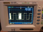
The pictures below show the half-bridge circuit, and the nasty oscillations on the high-side MOSFET gate.

Any ideas on what could be causing this? Many thanks in advance...
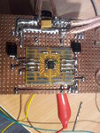
Motor Driver Circuit.jpg

Oscillations.jpg
 

- the bus voltage and driver supply decoupling seems insufficient
- feedback to the driver logic input due to ground inductances should be considered as possible oscillation mechanism. You should be able to determine it by comparing the voltage levels at both sides of the 10 ohm gate resistor.
 

Hi,

O.K., so I've currently got:
100nF -> Vdd decoupling
220uF + 15uF -> Driver decoupling

Should I add some more 100nF's for Vdd decoupling or should I choose larger capacitances?

The 220uF and 15uF are pretty large driver decoupling caps, are you thinking I should add some smaller values (and hence lower ESR) too? (e.g. 100nF)?

I never considered coupling back into the logic input (IN on the diagram below)! I don't quite understand how measuring the voltages either side of the 10Ohm gate resistor would show this?

Below is the application diagram for the chip. I have done everything there except put in the optional fast recovery diode.

LM5104 Example Circuit.JPG
 

O.K., so I've currently got:
100nF -> Vdd decoupling
220uF + 15uF -> Driver decoupling

Should I add some more 100nF's for Vdd decoupling or should I choose larger capacitances?
220 + 15 u sounds acceptable for the time being, but a single 100n capacitor seems pretty low, I would prefer e.g. 1 u in this place. What's your bootstrap capacitor value?

I never considered coupling back into the logic input (IN on the diagram below)! I don't quite understand how measuring the voltages either side of the 10Ohm gate resistor would show this?
Due to the low input threshold of 1.8 V, the IN terminal seems rather succeptible to interferences. The idea is to see, if the driver output tries to keep it's state during oscillations or rather stokes them.

By the way, how do you measure high side gate voltage? Do you have a differential probe?
 

What's your bootstrap capacitor value?

330nF. The total gate charge of the MOSFET is 70nC when Vgs = 10V. The cap holds 2970nC when charged up to 9V (the supply voltage), so the gate requires 2.3% of the total available charge.

Due to the low input threshold of 1.8 V, the IN terminal seems rather succeptible to interferences. The idea is to see, if the driver output tries to keep it's state during oscillations or rather stokes them.

Ahhh right, so if the driver side of the 10Ohm had noticeably less oscillation than the MOSFET gate side, you could rule out feedback, but if the driver side oscillated as much as the gate, it might indicate feedback.

By the way, how do you measure high side gate voltage? Do you have a differential probe?

Duoh! Forgot it's source is not tied to ground, hence that osc image is not the gate-source voltage but rather the gate to circuit ground. I don't have a differential probe, but I could use the two channels of the osc and you the MATH function, although I have found it to be rather inaccurate and good for nothing in the past...
 

that osc image is not the gate-source voltage but rather the gate to circuit ground.
In this case, I don't really understand the waveform, because the gate voltage should swing between zero and VBUS+VDD. What's VBUS for this measurement?
 

The BUS voltage is 9V, and the driver (VDD) voltage could of been anywhere between 1 an 15V (I was varying it with a power supply). Since the scope reads a little over 15V, I'm guessing VDD would of been about 6.5V at that time I took the photo.
 

I'm guessing VDD would of been about 6.5V at that time I took the photo.
In this case, the result is unpredictable, and the observed waveform may be even "normal" operation, because VDD is at the undervoltage lockout threshold.
 

Sorry, by VDD I assumed we were talking about the 'half-bridge' voltage (voltage across the MOSFET half-bridge) instead of the bus voltage (supply voltage to the IC, called Vdd in the datasheet).

The IC voltage (Vdd) is 9.0V.

The half-bridge voltage is 6.5V at the time of measurement.
 

feedback to the driver logic input due to ground inductances should be considered as possible oscillation mechanism. You should be able to determine it by comparing the voltage levels at both sides of the 10 ohm gate resistor.

FvM, you were right about the problem being from the feedback. I shortened the input pulse as much as possible, which improved it somewhat. Then I added a 100pF cap from the input to ground (essentially decreasing the input impedence, making it harder for noise to cross-over), which fixed all oscillation problems. The motor driver works smoothly at 18kHz.

Thanks :)
 

Status
Not open for further replies.

Part and Inventory Search

Welcome to EDABoard.com

Sponsor

Back
Top