Continue to Site

Welcome to EDAboard.com

Welcome to our site! EDAboard.com is an international Electronics Discussion Forum focused on EDA software, circuits, schematics, books, theory, papers, asic, pld, 8051, DSP, Network, RF, Analog Design, PCB, Service Manuals... and a whole lot more! To participate you need to register. Registration is free. Click here to register now.

Gyrator implementation of chip inductor

Status
Not open for further replies.

promach

Advanced Member level 4
Joined
Feb 22, 2016
Messages
1,202
Helped
2
Reputation
4
Reaction score
5
Trophy points
1,318
Activity points
11,643
" Increasing current would look easy, but it will affect your current source's bias margin reducing CMRR. Increasing current will reduce the gain. But varying Rs will not give you a great range, but will not affect your dc operating much as it carries incremental current. "

Could anyone elaborate more on the statement above possibly with some other references, diagrams or equations ?
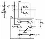
FgKeE.png
 

Can't find Rs in your schematic. Is it the "8bit" source-to-source resistor (shown as poti)?
 

Yes, Rs is the resistor with the label <7:0>
 

I am still quite confused on the two accuracy knobs (Rs<7:0> and current source<2:0>). Would anyone be able to explain the maths behind ?
 

Rs<7:0> means 8 equal resistors in parallel. The potentiometer arrow could mean its total resistance should be adjusted (to a reasonable value), or can be adjusted by clipping the connection(s) of one or more of these parallel resistors.

The current source<2:0> means 3 current sources; the master source isn't shown - just the 2 slave sources.
 

" Increasing current would look easy, but it will affect your current source's bias margin reducing CMRR. Increasing current will reduce the gain. But varying Rs will not give you a great range, but will not affect your dc operating much as it carries incremental current. "

I am bit confused on this statement. I am looking for equations that could explain more.
 

Asking about an answer giving in a different forum without at least a link to the original discussion is rather impertinent.

https://www.designers-guide.org/Forum/YaBB.pl?num=1483949730/4

Both discussions are however lacking a reference to the original literature (the source of the schematic), which in case of doubt explains more.

You are asking for equations, did you already derive the circuit parameters gm, rout in dependency of ib and Rs?

My basic thought is that for a strongly degenerated differential pair, the effective gm doesn't depend much on ib. Which parameter is however addressed with "gain" in the discussion? gm increases rather than decreases with ib, rout decreases of cause.
 

The author of the original paper Behzad Razavi has apparently chosen circuit parameters in a specific way.

With a Q of 15, this circuit requires sufficiently fine tuning steps, hence the need for a coarse control (the tail currents) and a fine control (the degeneration resistance).

To make tail current ib the coarse control, degeneration must be weak (relative small Rs value). This design decision can't be viewn from the schematic. I just presume that the expert knows well what he's doing. As the paper has no quantitative data of the gyrator design, it's more sketching a design idea than giving a template. You might play around with circuit parameters to guess what Razavi's design parameter are.

The statement quoted in your initial post seems to miss the specific design decision in the paper.
 

@FvM

I have looked at Fig. 3.15 on page 36 of the attached thesis. There is no mention regarding the adjustable Ib and Rs knobs.

Anyone have any other idea ?
 

Attachments

  • RF Synthesis without Inductors_2016.pdf
    2.1 MB · Views: 145

Interestingly, the statement about coarse and fine control can't be found in the thesis, I guess it's still right. At least parameters for gm3, gm4 and CL can be found.
 

Maybe this helps you. I am not definitely sure it is correct or not.


Leq.png

sorry for my bad handwriting.

Now you may replace Gm2= gm6/(1+Rs*gm6)

if you increase Rs you are decreasing Gm2 so your inductor will increase.

If you increase the current source you increase Gm2 (but it has minor effect since it is source degeneration and Gm2 mostly depends on Rs). for higher gm6 -> Gm2 = 1/Rs
 

Now you may replace Gm2= gm6/(1+Rs*gm6)

if you increase Rs you are decreasing Gm2 so your inductor will increase.

If you increase the current source you increase Gm2 (but it has minor effect since it is source degeneration and Gm2 mostly depends on Rs). for higher gm6 -> Gm2 = 1/Rs

Why minor effect ? There is no terminology on current source in the equation of Gm2 due to small-signal nature.
 

If you increase the current source you increase Gm2 (but it has minor effect since it is source degeneration and Gm2 mostly depends on Rs). for higher gm6 -> Gm2 = 1/Rs.
This was also my first assumption (see post #7), but according to the paper linked in post #8, it's not true for this circuit implementation, (see post #9). Rs is apparently relative small so that it only provides a fine adjustment of total gm.


The statement about fine control provided by the degeneration resistance. That's only possible if gm is not dominated by Rs, respecitively Rs << 1/gm
 

Why minor effect ? There is no terminology on current source in the equation of Gm2 due to small-signal nature.


Gm2= gm6/(1+Rs*gm6)

if you increase current you will increase gm6 and if you increase gm6 then gm6*Rs >> 1 therefore, Gm2=gm6/(Rs*gm6) = 1/Rs so for higher currents Gm2 is constant

- - - Updated - - -

This was also my first assumption (see post #7), but according to the paper linked in post #8, it's not true for this circuit implementation, (see post #9). Rs is apparently relative small so that it only provides a fine adjustment of total gm.

yeah thats true. if Rs is small gm6 will effect overal Gm2.
 

OK.

Gm2= gm6/(1+Rs*gm6) = 1/((1/gm6) + Rs)

How do we see from this equation that gm6 is coarse accuracy knob and Rs is fine accuracy knob ?
 

for Rs=100

gm.png

Generally you dont choose small value for Rs since you want to have a linear gm if you put Rs the Gm2 = 1/Rs for high currents.

If you dont put Rs then Gm2=gm6 which is not linear.

gm2.png

So you want overall Gm to be independent of gm6

Therefore, gm6 should be sufficiently high. Rs should be high too but if you increase Rs too much it will decrease your overal Gm=1/Rs
 

@Ata_sa16

Generally you dont choose small value for Rs since you want to have a linear gm

Could you shed more lights on your statement above ?


https://www.desmos.com/calculator/1xnutgseca

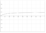
I have plotted a simple graph for Rs=100, 200 and 300 respectively. Note: y represents Gm2 , x represents gm6

jKPBaBk.png
 

Attachments

  • Screenshot from 2017-08-06 20-53-47.png
    Screenshot from 2017-08-06 20-53-47.png
    82.1 KB · Views: 129

Status
Not open for further replies.

Part and Inventory Search

Welcome to EDABoard.com

Sponsor

Back
Top