Continue to Site

Welcome to EDAboard.com

Welcome to our site! EDAboard.com is an international Electronics Discussion Forum focused on EDA software, circuits, schematics, books, theory, papers, asic, pld, 8051, DSP, Network, RF, Analog Design, PCB, Service Manuals... and a whole lot more! To participate you need to register. Registration is free. Click here to register now.

Gradually increasing 12 VDC LED lighting circuit.

Status
Not open for further replies.

Matrooo69

Newbie level 2
Newbie level 2
Joined
Jan 12, 2015
Messages
2
Helped
0
Reputation
0
Reaction score
0
Trophy points
1
Activity points
17
I need help on a DIY LED lighting project for a remote location. I am trying to set up a motion activated 12VDC lighting circuit that will gradually light up an LED over a 180 second period. It will be set up in remote locations and use a 12 volt battery and a solar charger. There are plenty of motion activated, battery powered LED lighting systems on the market but none that I could find that will gradually increase the lighting over several minutes. Is there an "off the shelf" devise that I can purchase and add to an existing LED circuit that will gradually increase the current to the LED or will I have to build something from scratch?

Any help or advise would be appreciated.
 

I think your vision's response to brightness is logarithmic (twice the amount of light appears only a little brighter) so a linear 3 minute ramp will probably be wrong for your application.
But your 3 minute ramp is such a long time that you probably cannot remember the brightness 20 or 30 seconds ago or a minute or two ago, so maybe a linear ramp will be fine.
I doubt that anybody makes such a thing so design and build it from scratch.
 

This setup is being built to monitor wild animals at remote locations so the gradual ramp up of light over 3 minutes is needed to keep from spooking the animals. The sudden switching on of light drives the animals away.
 

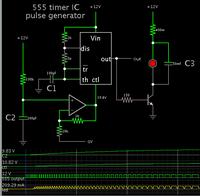
Here is a concept which might work.

You can vary the duty cycle from a 555 timer IC, by changing the voltage at its 'CTL' pin. Start a capacitor charging (C2 in the simulation below), feed its voltage to an op amp, and apply it to increase the duty cycle.


The scope trace covers a period of 34 seconds. The pulse rate is slowed down to make individual waveforms obvious.

In a real circuit, reduce C1 so pulse rate is faster.

Also reduce C3. Its purpose is to smooth the pulses through the led. Or else you might prefer to put a choke inline.
 

Status
Not open for further replies.

Part and Inventory Search

Welcome to EDABoard.com

Sponsor

Back
Top