samiurrehman
Member level 2


Very true: you have to use the capacitor as feedback element (to the negative input).... the circuit quite well acts as a low pass filter after installation of capacitor at the end...
I believe just a capacitor at the end can't transform an amplifier into integrator......


What you've done is OK so far. Try putting to the output one more transconductor with negative feedback. Then you'll have three elements: OTA (which acts as a V-I converter) + C (which is teh integrating element) + OTA - neagtive feedback (active resistance). Your integrator is then the active equivalent of a classical RC lowpass circuit.
Gm-C circuits are very well described by Schauman or Sansen & Laker
... Sansen & Laker........
Dear all,
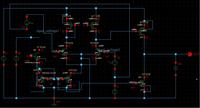
... there is one major problem i am facing, the integrator BW problem. ....Cap i am using in image 2 is 47uF.........
Well, a capacitor of uF is MUCH MUCH to big for Gm-C circuits. Try using only pF caps if you design specifications allow this. A rule o thumb (and nothing scientific in this statement): the bigger the capacitor, the lower the BW.
On the other hand, you can (slightly) adjust the integrator gain and BW out of the OTA bias currents. This of course presuming that the OTAs are already designed for your specifications.
Again, your pole is gm2/C. By increasing C you don't make it behave like an ideal integrator, all you do is move the cut-off frequency lower, out of the range you are plotting. If you plot lower frequencies you will still see it. It will only be a quasi-ideal integrator for frequencies above the cut-off. To increase the gain at a certain frequency (or the "integrating BW" as you say!), you need to increase the dc gain of the LPF. See the comments on my previous post.Dear Phoibus,
Sure i totally agree with your rule of thumb but you know i am talking about the integrator BW (the slope, in a LPF for example)....If i use cap with less value my integrator acts more like a LPF, to eliminate the LPF BW, i used a large cap that is why i am getting just a tappered slope as AC response which matches with ideal integrator response. But this integrating BW reduces with the LPF BW.....this BW goes down the same with LPF BW.....
Can you provide with some material on Gm-C circuits??
Regards
Dear LvW,
The integrator i designed has some problems.....It's integrating BW is very small...Actually i am still confused as to what are the characteristics of an ideal integrator.....now how do i demonstrate that i have built a nice integrator...it does not convert pulse into triangular......but can operate at 2G Hz....its a Gm-C integrator........My integrator has to be used in "digital modulator" used in RF front end....research is still underway...
Regards
We use cookies and similar technologies for the following purposes:
Do you accept cookies and these technologies?
We use cookies and similar technologies for the following purposes:
Do you accept cookies and these technologies?
