Continue to Site

Welcome to EDAboard.com

Welcome to our site! EDAboard.com is an international Electronics Discussion Forum focused on EDA software, circuits, schematics, books, theory, papers, asic, pld, 8051, DSP, Network, RF, Analog Design, PCB, Service Manuals... and a whole lot more! To participate you need to register. Registration is free. Click here to register now.

Getting Error during Annotation of DC and Current using AWR MWO

narayani

Full Member level 2
Full Member level 2
Joined
Aug 15, 2014
Messages
133
Helped
0
Reputation
0
Reaction score
1
Trophy points
1,298
Activity points
2,356
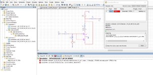
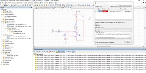
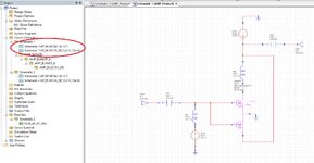
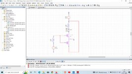
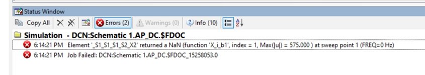
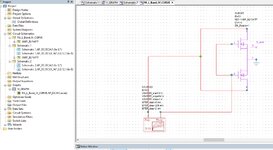
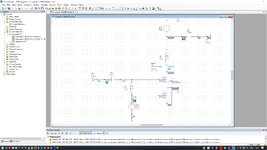
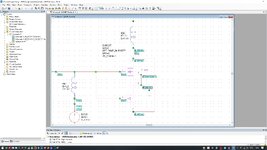
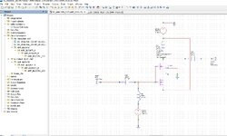
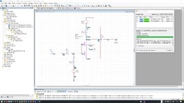
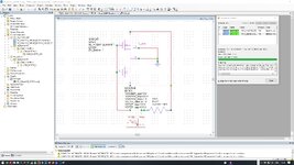
I am getting error during annotation of DC Voltage and current using AWR MWO. I am not able to find out how to get rid of this error. Actually I wanted to check biasing condition for Power Amplifier.
 

Attachments

  • DC_Annonation_Schematic_Error.jpg
    DC_Annonation_Schematic_Error.jpg
    472.2 KB · Views: 72
  • DC_Annonation_Schematic_Warning.jpg
    DC_Annonation_Schematic_Warning.jpg
    660.3 KB · Views: 68
  • DC_Annonation_Schematic.jpg
    DC_Annonation_Schematic.jpg
    451 KB · Views: 76
I have followed exactly same steps given in the MWO Getting Started guide. But I am getting error for my circuit and am not able to find what is the error?
 

Attachments

  • Schematic_1.jpg
    Schematic_1.jpg
    642.5 KB · Views: 80
  • Error_Message.jpg
    Error_Message.jpg
    60.8 KB · Views: 85
  • Informatic_About_Schematic.jpg
    Informatic_About_Schematic.jpg
    487.2 KB · Views: 53
  • MWO_Example.jpg
    MWO_Example.jpg
    61.8 KB · Views: 53
I believe that is a compatibility problem. Or it's a particular isue.
Even I am not able to plot IV Curve plot that is also showing error. I have attached AWR MWO IV Curve plot file.
I have also attached IV Curve plot and error message. I am struck, someone can suggest me to move ahead.
 

Attachments

  • Error_Message.jpg
    Error_Message.jpg
    558.9 KB · Views: 75
  • IV_ckt.jpg
    IV_ckt.jpg
    301.2 KB · Views: 45
  • MWO_FILE.zip
    53.9 KB · Views: 37
Maybe this is some "divide by zero" error in the model, because it happens at I=0 and f=0. Have you tried to start from a non-zero current?
 
You have to refer Cadence Technical Support to overcome this problem.
It's evidently a compatibility problem so the model itself is either not compatible with version which you've been using OR the model has bugs.
 
Hi Narayani! The problem are solved in these ways.
 

Attachments

  • Schematic1.jpg
    Schematic1.jpg
    1 MB · Views: 56
  • Schematic1_2.jpg
    Schematic1_2.jpg
    687.2 KB · Views: 48
Last edited:
Shorting all the pins of the MOSFET at the bottom, I don't think it's a solution..
From the developer's design, it is unclear how many transistors of the BLF647P assembly should be used in the circuit. If it is one, then the lower transistor should be excluded from the DC calculation by shorting all its terminals. Otherwise, the upper and lower transistors will short-circuit L2 and DCVS ID_V2 V= 32V. If the transistors are intended to operate in parallel, then the circuit needs to be configured in the second way.
 
I have attached AWR MWO DC Analysis 18 version .emp file. Generate DC annotation for this file
 

Attachments

  • MWO_DC_ACANALYSIS.zip
    34.8 KB · Views: 40
Hi Narayani! This is what I got after simulation
 

Attachments

  • DC-Analysis_CKT.jpg
    DC-Analysis_CKT.jpg
    1.1 MB · Views: 25
  • PA_1_Band.jpg
    PA_1_Band.jpg
    867.4 KB · Views: 25
  • IV Graf.jpg
    IV Graf.jpg
    830.8 KB · Views: 23
  • BLF647P.zip
    58.6 KB · Views: 25

LaTeX Commands Quick-Menu:

Part and Inventory Search

Welcome to EDABoard.com

Sponsor

Back
Top