Continue to Site

Welcome to EDAboard.com

Welcome to our site! EDAboard.com is an international Electronics Discussion Forum focused on EDA software, circuits, schematics, books, theory, papers, asic, pld, 8051, DSP, Network, RF, Analog Design, PCB, Service Manuals... and a whole lot more! To participate you need to register. Registration is free. Click here to register now.

Gerber design

Goldenshuttle

Member level 3
Member level 3
Joined
Sep 30, 2011
Messages
58
Helped
0
Reputation
0
Reaction score
0
Trophy points
1,286
Location
North York
Activity points
1,801
How much time do I need to design a PCB for this circuit ?
Audioservomod.JPG
ICS.JPG
 
I wonder how one ask this question not giving any relevant information related to the topic...What CAD? Have footprint libraries? Previous experience? 1 or 2 Layers? Size constraint? How urgent is this and what is your level of involvement? How etc...? As you can see, it has not a straight answer.
 
An impossible question to answer without more details.
Are the components through hole or surface mount?
What size constraints do you have (board dimensions)?
There are three potentiometers, are they board mounted and if so, do they have to be in fixed locations to match the enclosure?
There are three LEDs, do they need to be in a fixed location to match the enclosure?

If you want a "ball park" answer, I would estimate 2 - 3 hours using Kicad if all the above were known.

Brian.
 
Hi,

no power supply, not even decoupling capacitors.
After you finished the PCB job .. how long will it take to debug it? .. to make it reliably working.

Klaus
 
Can you describe your own learning curve, experience with design and software skills?

This question is unanswerable. But I would expect a few days to get it right the 1st time or an hour with some experience with auto-routing tools.

Do you know pots have pin numbers? and the frequency deviates since this design is not a true PWM but rather PFM.
 
How long depends on how long you've done something like this before.

Why are you choosing this design?
Thanks for commenting. I need to make a neat PCB for a talking mouth servo. I always used strip board but this one I want to make a proper PCB, maybe order 5 pcs online as they quoted me 2.5$/pc but they wanted a gerber file.... No experience on gerber PCB design, or what software to use..usually using my head to work around strip board. is there a free software to do it or i need to buy a license.?
--- Updated ---

An impossible question to answer without more details.
Are the components through hole or surface mount?
What size constraints do you have (board dimensions)?
There are three potentiometers, are they board mounted and if so, do they have to be in fixed locations to match the enclosure?
There are three LEDs, do they need to be in a fixed location to match the enclosure?

If you want a "ball park" answer, I would estimate 2 - 3 hours using Kicad if all the above were known.

Brian.
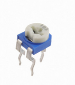
Thanks BetWixt. im using normal componenets not sufrace mount. LEDs 5mm sitting in the PCB. the pots are small presets like these below...no exact constraints I was thinking 2x2 inch maybe enough.1707107939731.png
 
Last edited:
Gerber isn't a PCB format but it can be used for PCBs. It is a format used in many industries where a 2D design has to be converted to a moving point, in the case of PCBs it holds the X and Y coordinates of the start and finish of every line. Basically, it tells the pen/cutter/laser or whatever to stop and start and to move between different locations so the original image is copied as a tangible object.

PCB manufacturers usually accept Gerber files because they are a well standardized system, some will accept design files in the format that different PCB design packages produce but you risk errors and incompatibility. Most PCB design programs, Kicad, Eagle etc. will convert and export your on-screen design into several Gerber files automatically and you can send those files straight to the manufacturer.

You normally have to send them a Gerber file for the track layout, another Gerber file for the solder mask and one for the drilling map. The tracks and solder mask will be one pair per layer of board so you would have four files for a double sided board. You may also send a Gerber with the screen printing information if you want a logo or part numbers printing on the board, again one for each side..

Brian.
 

LaTeX Commands Quick-Menu:

Similar threads

Part and Inventory Search

Welcome to EDABoard.com

Sponsor

Back
Top