Continue to Site

Welcome to EDAboard.com

Welcome to our site! EDAboard.com is an international Electronics Discussion Forum focused on EDA software, circuits, schematics, books, theory, papers, asic, pld, 8051, DSP, Network, RF, Analog Design, PCB, Service Manuals... and a whole lot more! To participate you need to register. Registration is free. Click here to register now.

Generating nice Sine wave

Status
Not open for further replies.

nerginer

Newbie level 5
Newbie level 5
Joined
Aug 12, 2006
Messages
9
Helped
0
Reputation
0
Reaction score
0
Trophy points
1,281
Activity points
1,364
Hi,
I will use a micro-controller to generate 0-5v sine wave but what I need is a +12 -12v sine wave. Can someone help me to design an opamp analog circuit?

Regards,
Nuri Erginer
 

Dear Nuri
Hi
You have two choice here :
1- obtain it from your sine wave of micro ( with adding some auxiliary circuits) .
2- Use a simple phase shift oscillator or wien bridge oscillator or the other types of sine wave oscillators.
So what is your choice ? ( at both of them i can help you ).
Best Wishes
Goldsmith
 

What I am looking for is a nice 50hz sine wave between -12v and +12v. The cheapest and simplest way is the best for me without back down the quality of the sine wave.
 

hummmm ! i think the wien bridge is cheapest and better way for you !
Regards
Goldsmith
 

I have look at the wien bridge a lot but can not find a proper solution. There are lamps vs in the circuit. I try to use intersil 8038 but it is too expensive. I forgot to tell you that the circuit will be powered with battery for example 2x12v battery. I am not an electronic expert that is why I need your help. Any help is welcome.
 

What do you mean by lamp ?
The wien bridge oscillator is something like this :
wien bridge oscillator.JPG
And F=1/2*pi*R*c
C1=C2 and R3=R4
And you can use a potentiometer instead of R1 to calibrate the out put without distortion.(about 20K ohms ).
Good luck
Goldsmith
 
  • Like
Reactions: dselec

    dselec

    Points: 2
    Helpful Answer Positive Rating
There are two ways to generate a sine wave using a micro-controller directly but you would still need some amplification to reach 24V p-p output:
1. generating numeric values of points along the sine wave and feeding them in sequence to a DAC.
2. with single bit using PWM to model the shape of the waveform.

Both methods can produce a wave with peaks at VCC and ground potential so you would need an amplifier with gain of about 5 times to reach the level you need.

Brian.
 

Hello Dear Brian
I as he mentioned at top , he want cheapest way , and i think a simple wien bridge oscillator will be more cheaper than a micro controller and filter and amplifier . isn't it ?
Best Regards
Goldsmith
 

It is a great honer to be in a such a place with full of helpful people. Yes I said micro-controller because I can only produce a sine wave between 0v 5v with a look up table. My background is programming.
But if it is possible to generate a sine wave cheaper and better with analog circuit I can use it. I will list below the constraints that I have. This may help us to go to the correct way.

1- cheaper is better but nice sine wave
2- battery powered ex: 2x12volt
3- 50hz -12v to +12v sine wave

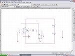
BTW :Goldsmith your circuit is not working in my simulator (isis proteus) can you re-check please

Regards,
Nuri Erginer
 

It is natural that it didn't work ! you should make a transient shock or a transient value such as IC probe . thus it can work .
Respect
Goldsmith
 

As I said I am not an expert so I need your guidance alot. Please find attached your circuit that I try to simulate in ISIS. goldsmith.jpg
 

No no no no no no ! those values are not correct ! those are default values of pspice . ( that i posted ) . and you should refer to post #6 , i told that what are the formulas of design .
Good luck
Goldsmith
 

Amplifier... simple audio amplifier... Google it
Next decide what u want... cheap and clean no distortion = wien bridge or RC shift oscillator
expensive =micro with distortion u will get from a/d conversion
about 20$ worth = pic controller with distortion from a/d
good luck
 
Last edited:

No no no no no no ! those values are not correct ! those are default values of pspice . ( that i posted ) . and you should refer to post #6 , i told that what are the formulas of design .
Good luck
Goldsmith

In the circuit diagram in posting#6 is an error: The resistor between opamp output and the inv. input must be twice the value of the R between the inv. input and ground.
That is the reason that nerginer's simulation failed.
 

Hello Dear dselec
And what about price ? he wanna do it with cheaper way .
Regards
Goldsmith
 

Do you need this 50Hz for an inverter? In that case, the best choice would be to implement SPWM. You can google on this for more info.

Use the micro to generate 2/4 PWM outputs (using SPWM; you'll probably be using a sine look up table as trigonometric function on the go would be too demanding for the micro). Connect this to driver and drive 4 MOSFETs in full-bridge converter and use a transformer to step up.

This would be more efficient than a simple analogue solution. And you won't hamper the sine wave much, depending on the filter. You can get very good output.

Hope this helps.
Tahmid.
 
Dear Tahmid
Hi
How are you my friend ?
i think if , he don't want inverter , it is not good way to achieve this sine wave from SPWM , because the output is not pretty pure and he will need high order filter and some feed backs , because it's frequency is low .
Best Wishes
Goldsmith
 

Yes, you are right. I assumed that it was for inverter. If it is not for inverter, then this is not the best method.
 

Hello gold
"I will use a micro-controller" so all he needs is a op 5$ audio amp or 500$ audio amp he has not told us what is the power .
"+12 -12v sine wave " he can get with 24vdc or +/- 12v supply or with special 4 quadrant amp he will get it even with 12v car batt.
 

Status
Not open for further replies.

Part and Inventory Search

Welcome to EDABoard.com

Sponsor

Back
Top