Continue to Site

Welcome to EDAboard.com

Welcome to our site! EDAboard.com is an international Electronics Discussion Forum focused on EDA software, circuits, schematics, books, theory, papers, asic, pld, 8051, DSP, Network, RF, Analog Design, PCB, Service Manuals... and a whole lot more! To participate you need to register. Registration is free. Click here to register now.

General I2C drive not receiving nor sending any data in EFR32FG14

Status
Not open for further replies.

yefj

Advanced Member level 5
Joined
Sep 12, 2019
Messages
1,505
Helped
1
Reputation
2
Reaction score
5
Trophy points
38
Activity points
9,113
Hello ,I want to communicate with my SI7021 with I2C drive of silicon labs using efr32fg14.
From the useguide manual shown bellow i got the ports needed.
API from the link bellow Was used to write a code as shown bellow.
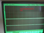
SCL and SDA are running on my four scope photos as shown bellow,So something is active there.I cant recognise the patterns shown of the data sheet shown bellow from the scope.I tried to use the debugger but it showed me BLANK "" value of buf variable on every step no matter what as shown in the printscreen bellow.

How can i see the scope photos and recognise the meening of what going on from the data sheet diagram?
Thanks.


1606233130946.png

1606233009095.png


1st scope
1606232632788.png

2nd scope
1606232664940.png

3rd scope
1606232701794.png

4th scope
1606232722184.png


1606231645900.png


1606231624847.png


Code:
#include "stddef.h"

#include "em_system.h"

#include "em_device.h"

#include "em_chip.h"

#include "em_cmu.h"

#include "em_emu.h"

#include "em_gpio.h"

#include "i2cspm.h"

#include "si7013.h"

#include "sl_sleeptimer.h"

#include "graphics.h"

#include "em_adc.h"

#include "bspconfig.h"


uint8_t com1[1] = {0xE3};

uint8_t i2c_rxBuffer[3];

int main(void)

{

I2C_TransferSeq_TypeDef i2cTransfer;

I2C_TransferReturn_TypeDef result;


I2CSPM_Init_TypeDef i2cInit = I2CSPM_INIT_DEFAULT;


/* Chip errata */

CHIP_Init();


// Enabling clock to the I2C, GPIO, LE

CMU_ClockEnable(cmuClock_I2C0, true);

CMU_ClockEnable(cmuClock_GPIO, true);

CMU_ClockEnable(cmuClock_HFLE, true);


// Starting LFXO and waiting until it is stable

CMU_OscillatorEnable(cmuOsc_LFXO, true, true);


I2CSPM_Init(&i2cInit);

// In order to enable the I2C0_SCL function in PC10 you need to use ROUTE 14

// In order to enable the I2C0_SDA function in PC11 you need to use ROUTE 16

//Also note that there's a GPIO pin PD15 that need to be set to high in order to route the signals to the sensor,

// Using PC10 (SCL) and PC11 (SDA)

  GPIO_PinModeSet(gpioPortC, 10, gpioModeWiredAndPullUp, 1);

  GPIO_PinModeSet(gpioPortC, 11, gpioModeWiredAndPullUp, 1);


  //Si7021 switch on

  GPIO_PinModeSet(gpioPortD, 15, gpioModePushPull, 1);


  // Enable pins at location 15 as specified in datasheet

  I2C0->ROUTEPEN = I2C_ROUTEPEN_SDAPEN | I2C_ROUTEPEN_SCLPEN;

  I2C0->ROUTELOC0 = (I2C0->ROUTELOC0 & (~_I2C_ROUTELOC0_SDALOC_MASK)) | I2C_ROUTELOC0_SDALOC_LOC16;

  I2C0->ROUTELOC0 = (I2C0->ROUTELOC0 & (~_I2C_ROUTELOC0_SCLLOC_MASK)) | I2C_ROUTELOC0_SCLLOC_LOC14;

  i2cTransfer.flags=I2C_FLAG_WRITE_READ;

  i2cTransfer.addr=0x80;//address with write

  i2cTransfer.buf[0].data=com1[0];  // Measure Temperature, Hold Master Mode

  i2cTransfer.buf[0].len=2;    //2 bytes length


  i2cTransfer.buf[1].data=i2c_rxBuffer;

  i2cTransfer.buf[1].len=3;    //LS MS checksum

while(1)

{

  result=I2C_TransferInit(I2C0,&i2cTransfer);


  // Sending data

   while (result == i2cTransferInProgress)

   {

    result = I2C_Transfer(I2C0);

   }

}


}
 

Attachments

  • 1606232030733.png
    1606232030733.png
    943.6 KB · Views: 174

Hi,

your slow rising edge let´s me assume you don´t have proper external pullup resistors with correct value installed.
(There may be other reasons...)

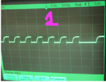
Only the third scope picture gives useful informations.
one can see:
* bus idle
* bus START
* sending address 0x80 + WRITE
* one even can recognize the ACK from the slave (a little higher LOW level during 9th bit)
* slave releases ACK
* then we just see the first 3 bits to be 0
... nothing else.

You need to learn how to use your scope. Try this:
* set timing to 10us/div
* trigger on falling edge of SDA after BUS IDLE. (to detect BUS IDLE you need to put a delay of 15ms or so.. depending on scope)
* set vertical zero for each channel exactly on a horizontal line
...
(I´ve chosen 15ms because the datsheet says that a humidity conversion may take up to 12ms, during this time the sensor may respond with NACK after the slave address)

******************
uint8_t com1[1] = {0xE3};
declares a buffer with one byte of size. But then you write
i2cTransfer.buf[0].len=2; //2 bytes length
.. which means the Tx buffer is 2 bytes in length. This can´t work satisfactory.

******************
You try to use command 0xE3 which is "measurement in hold master mode" which is clock stretching mode.
Don´t start with complicated things. (This command initiates a measurement, but does not give back any result. Please read documentation.)

I don´t recommend to use clock stretching
--> I rather recommend to start with "Read Firmware Revision", this is most simple command, without wait, but with known response.

Klaus
--- Updated ---

Read this:
 
Last edited:

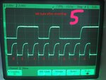
Hello Klause,I have updated the code bellow following your advices, I got a transmition from start to end.
Bellow we see the diagram of SI7021 sensor and the first two parts.
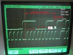
First We have Start -which is lowing the SDA when SCL is high.then we have 8 clock of data.
But In photo 3 at the start marked red,we dont have a drop in SDA while high clock, we only have 8 clocks which i assume are the data.
Where is the start? Could you please say what am i missing in reading this transmition?
You said E3 is too complicated command,What command you reccomend me to useso i would try and analize its scope waveforms.
Thanks.
1606661127511.png

1606660074753.png


1606660632572.png


1606660701384.png


1606660759946.png


Code:
#include "stddef.h"

#include "em_system.h"

#include "em_device.h"

#include "em_chip.h"

#include "em_cmu.h"

#include "em_emu.h"

#include "em_gpio.h"

#include "i2cspm.h"

#include "si7013.h"

#include "sl_sleeptimer.h"

#include "graphics.h"

#include "em_adc.h"

#include "bspconfig.h"


uint8_t com1[1] = {0xE3};

uint8_t i2c_rxBuffer[3];

int main(void)

{

I2C_TransferSeq_TypeDef i2cTransfer;

I2C_TransferReturn_TypeDef result;


 I2CSPM_Init_TypeDef i2cInit = I2CSPM_INIT_DEFAULT;


 /* Chip errata */

 CHIP_Init();


 // Enabling clock to the I2C, GPIO, LE

 CMU_ClockEnable(cmuClock_I2C0, true);

 CMU_ClockEnable(cmuClock_GPIO, true);

 CMU_ClockEnable(cmuClock_HFLE, true);


 // Starting LFXO and waiting until it is stable

 CMU_OscillatorEnable(cmuOsc_LFXO, true, true);


 I2CSPM_Init(&i2cInit);

 // In order to enable the I2C0_SCL function in PC10 you need to use ROUTE 14

 // In order to enable the I2C0_SDA function in PC11 you need to use ROUTE 16

 //Also note that there's a GPIO pin PD15 that need to be set to high in order to route the signals to the sensor,

 // Using PC10 (SCL) and PC11 (SDA)

  GPIO_PinModeSet(gpioPortC, 10, gpioModeWiredAndPullUp, 1);

  GPIO_PinModeSet(gpioPortC, 11, gpioModeWiredAndPullUp, 1);


// GPIO_PinModeSet(gpioPortC, 10, gpioModeWiredAnd, 1);

//  GPIO_PinModeSet(gpioPortC, 11, gpioModeWiredAnd, 1);

  //Si7021 switch on

  GPIO_PinModeSet(gpioPortD, 15, gpioModePushPull, 1);


  // Enable pins at location 15 as specified in datasheet

  I2C0->ROUTEPEN = I2C_ROUTEPEN_SDAPEN | I2C_ROUTEPEN_SCLPEN;

  I2C0->ROUTELOC0 = (I2C0->ROUTELOC0 & (~_I2C_ROUTELOC0_SDALOC_MASK)) | I2C_ROUTELOC0_SDALOC_LOC16;

  I2C0->ROUTELOC0 = (I2C0->ROUTELOC0 & (~_I2C_ROUTELOC0_SCLLOC_MASK)) | I2C_ROUTELOC0_SCLLOC_LOC14;

  i2cTransfer.flags=I2C_FLAG_WRITE_READ;

  i2cTransfer.addr=0x80;//address with write

  i2cTransfer.buf[0].data=&com1[0];  // Measure Temperature, Hold Master Mode

  i2cTransfer.buf[0].len=1;    //1 byte E3 measure temp command


  i2cTransfer.buf[1].data=i2c_rxBuffer;

  i2cTransfer.buf[1].len=3;    //LS MS checksum

while(1)

{

  result=I2C_TransferInit(I2C0,&i2cTransfer);


  // Sending data

   while (result == i2cTransferInProgress)

   {

    result = I2C_Transfer(I2C0);

   }

}


 }
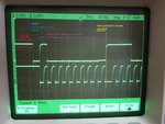
 

Scope pictures.

It should start with bus_idle = both signals are HIGH.

Klaus
 

Hello, I have finished encoding the I2C transmtion with Si7021 as shown in the step by step photos bellow.
at 1st we send start->Send slave address -> slave does ACK
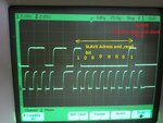
2nd then we send measure command which is 1110,0011->slave does ACK which is E3
3rd then we send slave address 1 lsb which is read-> ack by the slave
4th Clock streching(time to get the measurment)
5th MS byte 01101000 ->ack
6th LS byte 11001100 ->ack
7th chechsum 10101100->Nack->stop->IDLE

How see if the checksum result fits the MS and LS bytes


Code:
#include "stddef.h"

#include "em_system.h"

#include "em_device.h"

#include "em_chip.h"

#include "em_cmu.h"

#include "em_emu.h"

#include "em_gpio.h"

#include "i2cspm.h"

#include "si7013.h"

#include "sl_sleeptimer.h"

#include "graphics.h"

#include "em_adc.h"

#include "bspconfig.h"


uint8_t com1[1] = {0xE3};

uint8_t i2c_rxBuffer[3];

int main(void)

{

I2C_TransferSeq_TypeDef i2cTransfer;

I2C_TransferReturn_TypeDef result;


 I2CSPM_Init_TypeDef i2cInit = I2CSPM_INIT_DEFAULT;


 /* Chip errata */

 CHIP_Init();


 // Enabling clock to the I2C, GPIO, LE

 CMU_ClockEnable(cmuClock_I2C0, true);

 CMU_ClockEnable(cmuClock_GPIO, true);

 CMU_ClockEnable(cmuClock_HFLE, true);


 // Starting LFXO and waiting until it is stable

 CMU_OscillatorEnable(cmuOsc_LFXO, true, true);


 I2CSPM_Init(&i2cInit);

 // In order to enable the I2C0_SCL function in PC10 you need to use ROUTE 14

 // In order to enable the I2C0_SDA function in PC11 you need to use ROUTE 16

 //Also note that there's a GPIO pin PD15 that need to be set to high in order to route the signals to the sensor,

 // Using PC10 (SCL) and PC11 (SDA)

  GPIO_PinModeSet(gpioPortC, 10, gpioModeWiredAndPullUp, 1);

  GPIO_PinModeSet(gpioPortC, 11, gpioModeWiredAndPullUp, 1);


// GPIO_PinModeSet(gpioPortC, 10, gpioModeWiredAnd, 1);

//  GPIO_PinModeSet(gpioPortC, 11, gpioModeWiredAnd, 1);

  //Si7021 switch on

  GPIO_PinModeSet(gpioPortD, 15, gpioModePushPull, 1);


  // Enable pins at location 15 as specified in datasheet

  I2C0->ROUTEPEN = I2C_ROUTEPEN_SDAPEN | I2C_ROUTEPEN_SCLPEN;

  I2C0->ROUTELOC0 = (I2C0->ROUTELOC0 & (~_I2C_ROUTELOC0_SDALOC_MASK)) | I2C_ROUTELOC0_SDALOC_LOC16;

  I2C0->ROUTELOC0 = (I2C0->ROUTELOC0 & (~_I2C_ROUTELOC0_SCLLOC_MASK)) | I2C_ROUTELOC0_SCLLOC_LOC14;

  i2cTransfer.flags=I2C_FLAG_WRITE_READ;

  i2cTransfer.addr=0x80;//address with write

  i2cTransfer.buf[0].data=&com1[0];  // Measure Temperature, Hold Master Mode

  i2cTransfer.buf[0].len=1;    //1 byte E3 measure temp command


  i2cTransfer.buf[1].data=i2c_rxBuffer;

  i2cTransfer.buf[1].len=3;    //LS MS checksum

while(1)

{

  result=I2C_TransferInit(I2C0,&i2cTransfer);


  // Sending data

   while (result == i2cTransferInProgress)

   {

    result = I2C_Transfer(I2C0);

   }

}


 }
 

Attachments

  • 1.jpeg
    1.jpeg
    319.2 KB · Views: 142
  • 2.jpeg
    2.jpeg
    315.5 KB · Views: 116
  • 3.jpeg
    3.jpeg
    319.7 KB · Views: 112
  • 4.jpeg
    4.jpeg
    282.9 KB · Views: 121
  • 5.jpeg
    5.jpeg
    278.9 KB · Views: 111
  • 6_LS Byte.jpeg
    6_LS Byte.jpeg
    301.8 KB · Views: 113
  • 6B-all 9 bits extended_Ls_byte.jpeg
    6B-all 9 bits extended_Ls_byte.jpeg
    298.5 KB · Views: 128
  • 7_CheckSum_Byte.jpeg
    7_CheckSum_Byte.jpeg
    288.1 KB · Views: 114
  • 7B_CheckSum_full_no Ack.jpeg
    7B_CheckSum_full_no Ack.jpeg
    299.1 KB · Views: 141
  • 8.jpeg
    8.jpeg
    296.8 KB · Views: 114

Hi,

congratulations. Good job!
and the scope pictures are really useful.

Checksum: The datasheet gives the polynomal formula.
A quick internet search (you could do on your own ) gives this:
...even with calculation code

What pullup resistors do you use?

Klaus
 

Hello Klauss, thank you very much,I didnt use any extra pullup because its a wellded board,on bbread board i will try to use extra pullups.
I had a problem with I2C as follows:
I have made the code communicate with the sensor endlessly in while(1) loop as shown in the code bellow.
At first i flashed the code ,i have a good endless I2C communication.
But when i disconnect the board and connect it again then both SDA and SCL are HIGH (IDLE ) and no renewal of I2C communication.
This phenomen happens even when i dissconnect the SCOPE PROBES and connect them again.

The only way i found to renew the I2C communication is to flash the software again.
How do i prevent it to get stuck in the IDLE mode from these situations?
Thanks.


Code:
#include "stddef.h"

#include "em_system.h"

#include "em_device.h"

#include "em_chip.h"

#include "em_cmu.h"

#include "em_emu.h"

#include "em_gpio.h"

#include "i2cspm.h"

#include "si7013.h"

#include "sl_sleeptimer.h"

#include "graphics.h"

#include "em_adc.h"

#include "bspconfig.h"


uint8_t com1[1] = {0xE3};

uint8_t i2c_rxBuffer[3];

int main(void)

{

I2C_TransferSeq_TypeDef i2cTransfer;

I2C_TransferReturn_TypeDef result;


I2CSPM_Init_TypeDef i2cInit = I2CSPM_INIT_DEFAULT;


/* Chip errata */

CHIP_Init();


// Enabling clock to the I2C, GPIO, LE

CMU_ClockEnable(cmuClock_I2C0, true);

CMU_ClockEnable(cmuClock_GPIO, true);

CMU_ClockEnable(cmuClock_HFLE, true);


// Starting LFXO and waiting until it is stable

CMU_OscillatorEnable(cmuOsc_LFXO, true, true);


I2CSPM_Init(&i2cInit);

// In order to enable the I2C0_SCL function in PC10 you need to use ROUTE 14

// In order to enable the I2C0_SDA function in PC11 you need to use ROUTE 16

//Also note that there's a GPIO pin PD15 that need to be set to high in order to route the signals to the sensor,

// Using PC10 (SCL) and PC11 (SDA)

  GPIO_PinModeSet(gpioPortC, 10, gpioModeWiredAndPullUp, 1);

  GPIO_PinModeSet(gpioPortC, 11, gpioModeWiredAndPullUp, 1);


// GPIO_PinModeSet(gpioPortC, 10, gpioModeWiredAnd, 1);

//  GPIO_PinModeSet(gpioPortC, 11, gpioModeWiredAnd, 1);

  //Si7021 switch on

  GPIO_PinModeSet(gpioPortD, 15, gpioModePushPull, 1);


  // Enable pins at location 15 as specified in datasheet

  I2C0->ROUTEPEN = I2C_ROUTEPEN_SDAPEN | I2C_ROUTEPEN_SCLPEN;

  I2C0->ROUTELOC0 = (I2C0->ROUTELOC0 & (~_I2C_ROUTELOC0_SDALOC_MASK)) | I2C_ROUTELOC0_SDALOC_LOC16;

  I2C0->ROUTELOC0 = (I2C0->ROUTELOC0 & (~_I2C_ROUTELOC0_SCLLOC_MASK)) | I2C_ROUTELOC0_SCLLOC_LOC14;

  i2cTransfer.flags=I2C_FLAG_WRITE_READ;

  i2cTransfer.addr=0x80;//address with write

  i2cTransfer.buf[0].data=&com1[0];  // Measure Temperature, Hold Master Mode

  i2cTransfer.buf[0].len=1;    //1 byte E3 measure temp command


  i2cTransfer.buf[1].data=i2c_rxBuffer;

  i2cTransfer.buf[1].len=3;    //LS MS checksum

while(1)

{

  result=I2C_TransferInit(I2C0,&i2cTransfer);


  // Sending data

   while (result == i2cTransferInProgress)

   {

    result = I2C_Transfer(I2C0);

   }

}


}
 

Hi,

Sounds like an ESD problem.

Protect your microcontroller against ESD pulses. There are many threads here and huge informations in the internet..
Is there a really solid GND plane? Are the power supplies properly bypassed with ceramics capacitors?
Are no (unused) input pins left floating? Analog as well as digital, on every IC.
Use the watchdog feature to (at least) reset the microcontroller in case of a sfoftware hang.

Klaus
 
  • Like
Reactions: yefj

    yefj

    Points: 2
    Helpful Answer Positive Rating
Hello,Currently i managed to communicate I2C with Si7021(which is welded on the efr32fg14 starter kit) i wanted to take this data and to send it over SPI and UART simultaniosly.
using the expansion header of the board shown bellow.
i wanted to redirect recievedI2C data only to SPI which are PC9,8,7,6 in the expantion header of the kit which is location 11
I combined the I2C and SPI codes into one code called I2C->SPI shown bellow,and got the MS LS CHECKSUM bytes on the scope as shown in the photo bellow.

Then i tried to go a step further and make USART0 to send sensor data simultaniosly with SPI.
On the expansion head PA1,PA0 are UART

In the endI got the scope bellow where we se the uart transmition we SPI transmition and the code.
We see the advantage of spi (Its much faster).

There is no question i just shared my updated work with the community :)


starter kit user guide.


1607260817799.png


**broken link removed**


**broken link removed**

**broken link removed**


I2C->SPI&UART

Code:
#include "em_usart.h"
#include "em_ldma.h"

/////////////////
#include "stddef.h"
#include "em_system.h"
#include "em_device.h"
#include "em_chip.h"
#include "em_cmu.h"
#include "em_emu.h"
#include "em_gpio.h"
#include "i2cspm.h"
#include "si7013.h"
#include "sl_sleeptimer.h"
#include "graphics.h"
#include "em_adc.h"
#include "bspconfig.h"


uint8_t com1[1] = {0xE3}; //measure command
uint8_t com2[4] = {0x03,0x0F,0xFF,0xF0}; //spi data sending
uint8_t i2c_rxBuffer[3]; //[0]-MS [1]-LS [2]-CheckSum
void initUSART1 (void)
{
    CMU_ClockEnable(cmuClock_GPIO, true);
    CMU_ClockEnable(cmuClock_USART1, true);

    // Configure GPIO mode
    GPIO_PinModeSet(gpioPortC, 8, gpioModePushPull, 0); // US1_CLK is push pull
    GPIO_PinModeSet(gpioPortC, 9, gpioModePushPull, 1); // US1_CS is push pull
    GPIO_PinModeSet(gpioPortC, 6, gpioModePushPull, 1); // US1_TX (MOSI) is push pull
    GPIO_PinModeSet(gpioPortC, 7, gpioModeInput, 1);    // US1_RX (MISO) is input
    GPIO_PinModeSet(gpioPortF, 7, gpioModeInput, 1);    // delay gpio

    // Start with default config, then modify as necessary
    USART_InitSync_TypeDef config = USART_INITSYNC_DEFAULT;
    config.master       = true;            // master mode
    config.baudrate     = 1000000;         // CLK freq is 1 MHz
    config.autoCsEnable = true;            // CS pin controlled by hardware, not firmware
    config.clockMode    = usartClockMode0; // clock idle low, sample on rising/first edge
    config.autoCsEnable = true;            // CS pin controlled by  firmware
    config.msbf         = true;            // send MSB first
    config.enable       = usartDisable;    // Make sure to keep USART disabled until it's all set up
    USART_InitSync(USART1, &config);

    // Set USART pin locations
    USART1->ROUTELOC0 = (USART_ROUTELOC0_CLKLOC_LOC11) | // US1_CLK       on location 11 = PC8 per datasheet section 6.4 = EXP Header pin 8
                        (USART_ROUTELOC0_CSLOC_LOC11)  | // US1_CS        on location 11 = PC9 per datasheet section 6.4 = EXP Header pin 10
                        (USART_ROUTELOC0_TXLOC_LOC11)  | // US1_TX (MOSI) on location 11 = PC6 per datasheet section 6.4 = EXP Header pin 4
                        (USART_ROUTELOC0_RXLOC_LOC11);   // US1_RX (MISO) on location 11 = PC7 per datasheet section 6.4 = EXP Header pin 6

    // Enable USART pins
    USART1->ROUTEPEN = USART_ROUTEPEN_CLKPEN | USART_ROUTEPEN_CSPEN | USART_ROUTEPEN_TXPEN | USART_ROUTEPEN_RXPEN;


    // Enable USART1
    USART_Enable(USART1, usartEnable);
    ////////////////////////////////////////////
    //UART INITLIZATION

    USART_InitAsync_TypeDef init = USART_INITASYNC_DEFAULT;


     // Enable oscillator to GPIO and USART0 modules

     CMU_ClockEnable(cmuClock_USART0, true);

     // set pin modes for UART TX and RX pins
     GPIO_PinModeSet(gpioPortA, 1, gpioModeInput, 0);
     GPIO_PinModeSet(gpioPortA, 0, gpioModePushPull, 1);

     // Initialize USART asynchronous mode and route pins
     USART_InitAsync(USART0, &init);
     USART0->ROUTELOC0 = USART_ROUTELOC0_RXLOC_LOC0 | USART_ROUTELOC0_TXLOC_LOC0;
     USART0->ROUTEPEN |= USART_ROUTEPEN_TXPEN | USART_ROUTEPEN_RXPEN;

}//end usart init

int main(void)

{

I2C_TransferSeq_TypeDef i2cTransfer;

I2C_TransferReturn_TypeDef result;


I2CSPM_Init_TypeDef i2cInit = I2CSPM_INIT_DEFAULT;


/* Chip errata */

CHIP_Init();
initUSART1();


// Enabling clock to the I2C, GPIO, LE

CMU_ClockEnable(cmuClock_I2C0, true);

CMU_ClockEnable(cmuClock_GPIO, true);

CMU_ClockEnable(cmuClock_HFLE, true);


// Starting LFXO and waiting until it is stable

CMU_OscillatorEnable(cmuOsc_LFXO, true, true);


I2CSPM_Init(&i2cInit);

// In order to enable the I2C0_SCL function in PC10 you need to use ROUTE 14

// In order to enable the I2C0_SDA function in PC11 you need to use ROUTE 16

//Also note that there's a GPIO pin PD15 that need to be set to high in order to route the signals to the sensor,

// Using PC10 (SCL) and PC11 (SDA)

  GPIO_PinModeSet(gpioPortC, 10, gpioModeWiredAndPullUp, 1);

  GPIO_PinModeSet(gpioPortC, 11, gpioModeWiredAndPullUp, 1);


// GPIO_PinModeSet(gpioPortC, 10, gpioModeWiredAnd, 1);

//  GPIO_PinModeSet(gpioPortC, 11, gpioModeWiredAnd, 1);

  //Si7021 switch on

  GPIO_PinModeSet(gpioPortD, 15, gpioModePushPull, 1);


  // Enable pins at location 15 as specified in datasheet

  I2C0->ROUTEPEN = I2C_ROUTEPEN_SDAPEN | I2C_ROUTEPEN_SCLPEN;

  I2C0->ROUTELOC0 = (I2C0->ROUTELOC0 & (~_I2C_ROUTELOC0_SDALOC_MASK)) | I2C_ROUTELOC0_SDALOC_LOC16;

  I2C0->ROUTELOC0 = (I2C0->ROUTELOC0 & (~_I2C_ROUTELOC0_SCLLOC_MASK)) | I2C_ROUTELOC0_SCLLOC_LOC14;

  i2cTransfer.flags=I2C_FLAG_WRITE_READ;

  i2cTransfer.addr=0x80;//address with write

  i2cTransfer.buf[0].data=&com1[0];  // Measure Temperature, Hold Master Mode

  i2cTransfer.buf[0].len=1;    //1 byte E3 measure temp command


  i2cTransfer.buf[1].data=i2c_rxBuffer;

  i2cTransfer.buf[1].len=3;    //LS MS checksum

while(1)

{

  result=I2C_TransferInit(I2C0,&i2cTransfer);


  // Sending data

   while (result == i2cTransferInProgress)

   {

    result = I2C_Transfer(I2C0);

   }

   //When sending data ends
   //SPI sending data
   USART_SpiTransfer(USART1,i2c_rxBuffer[0]);
   USART_SpiTransfer(USART1,i2c_rxBuffer[1]);
   USART_SpiTransfer(USART1,i2c_rxBuffer[2]);

   //send UART
   USART_Tx(USART0, 0x61);
      USART_Tx(USART0, i2c_rxBuffer[0]);
      USART_Tx(USART0, i2c_rxBuffer[1]);
      USART_Tx(USART0, i2c_rxBuffer[2]);
      USART_Tx(USART0, '\n');

}


}
 

Attachments

  • 1607256391621.png
    1607256391621.png
    404.5 KB · Views: 88
  • 1607256627788.png
    1607256627788.png
    404.5 KB · Views: 95

Hi,

You say SPI is faster than UART.
Generally I agree, but you show really slow UART....just increase UART baud rate and it will be much faster than shown.

Klaus
 

Status
Not open for further replies.

Part and Inventory Search

Welcome to EDABoard.com

Sponsor

Back
Top