Continue to Site

Welcome to EDAboard.com

Welcome to our site! EDAboard.com is an international Electronics Discussion Forum focused on EDA software, circuits, schematics, books, theory, papers, asic, pld, 8051, DSP, Network, RF, Analog Design, PCB, Service Manuals... and a whole lot more! To participate you need to register. Registration is free. Click here to register now.

Garage door + Computer

Status
Not open for further replies.

lemmin

Newbie level 2
Newbie level 2
Joined
Jul 27, 2012
Messages
2
Helped
0
Reputation
0
Reaction score
0
Trophy points
1,281
Activity points
1,305
I had a project idea involving opening my garage door with an RFID reader. My knowledge is more on the software side of this project and I have a few questions about the electrical aspect:

My garage door opener is a Wayne Dalton 3220C. The wall switch is connected to a contact labeled P.B. and another common contact shared with the laser interrupt. I read 7.7v from the P.B. contact and I can output 4.2v from the parallel port on a Linux box. My three questions are:

1. Can I activate the switch by sending 4.2v to the common contact from my computer?
2. Is it safe to wire that with a Cat5 ethernet cable?
3. Is there any danger of damaging the computer if the laser interrupt sends it's 7.7v signal to the common contact?
4. Is there any danger of damaging the garage door opener by sending this lower voltage to it?

Thanks for any help.
 

Voltage is a difference in potential, not an absolute value. "Sending" 4.2V to contact will have unpredictable (ranging from nonfunctional to dangerous) results if the systems do not share a common reference point (and even if they do it will still have bad results, see below).

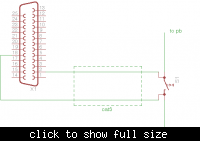
It sounds like this is your initial plan:


Do not do this! Connecting the ground and 4.2V and lines from your parallel port to the switch will do a few undesirable things:
  • It will bring your machine's power supply ground to the same potential as the "common" connector on your garage door circuit, which may or may not cause problems.
  • It will short your parallel port data pin to ground when you press the real garage door switch which is probably not a good idea.
  • It will cause the garage door circuit to drive all the current that would normally go through the switch through your parallel port instead, likely damaging your computer.
  • It will most likely not open your garage door, or will open it exactly once while frying your parallel port in the process.
The garage door circuit relies on being able to drive current through the switch when it is closed, your parallel port is not an appropriate device to close the circuit with.

One solution is to use a simple relay with the contacts across the garage door switch and the coil controlled by your parallel port buffered through an op amp or optoisolator. This is a very basic circuit, will maintain isolation between your parallel port and the garage door circuitry, won't damage your parallel port, and also won't interfere with the normal operation of your garage door switch. A relay is just a magnetically controlled switch. It basically simulates pressing the button, e.g.:


The reason for the buffer is because parallel ports can't really source enough current to drive a relay. AFAIK there is no standard minimum, they vary anywhere from 2-16mA, so your best bet is to assume the worst and don't pull more than 2mA from your parallel port (2.6mA is the limit given at **broken link removed**). The op amp will drive the relay coil through your computer's power supply instead of through the serial port.

In the above circuit:
  • GND represents your machine's ground (the parallel port grounds are already connected to it, it is shown in the circuit for clarification -- do not make that connection explicitly or you may create a ground loop).
  • VCC is the op-amps supply input and should be connected to a suitable power supply source from your computer (e.g. the +12V line from an ATX power supply).
  • R1 and R2 should be chosen to amplify the voltage to whatever the relay coil requires. E.g. a 5V relay would require a gain of 5/4.2 ≈ 1.2 and gain = (1+R1/R2) so e.g. R1 = 13K and R2 = 68K would get close enough (good tool: **broken link removed**) and would give you 5V out from your 4.2V in.
  • S1 is the existing garage door push button switch.
  • The relay switch is connected in parallel to your garage door switch. It should be connected to the normally-open side of the relay (energizing the relay coil will close the switch).

A word about choosing components and values:
  • VCC must be > required relay voltage with allowance for op-amp's maximum output swing (rail-to-rail op amp would be required if you only have 5V VCC and relay also requires 5V, single-supply op-amp required if you're using 0V for negative op amp supply as in my diagram, although you could always use e.g. the -5 or -12V atx line - but don't connect those to system ground! you'd run your relay off lpt ground pin and op amp output in that case).
  • Op-amp max output current (sometimes called source current) must be greater than current required by relay coil (I'd say 20%-50% greater to be safe).
  • Relay contact rating must be greater than current that normally flows through garage door switch (which is probably small). You can measure this by setting your meter to DC current mode and touching the probes to both sides of the switch (don't be surprised when this opens your garage door). Same with relay contact voltage rating. Again add 20%-50% to be safe.
  • CAT5 cable can handle it fine. CAT5 cable resistance IIRC is about 1.2Ω/100ft. which will be negligible for the distance I imagine you running it.

So you must choose a relay, op-amp, and VCC source that are compatible with eachother, then choose an appropriate R1 and R2 based on the relay voltage (btw see http://www.allaboutcircuits.com/vol_3/chpt_8/5.html for more good info on op amps). If you tell me what VCC options you have available and what the current going through your garage door switch is I can help you spec out parts.

You could avoid the whole buffering thing if you found an affordable 4.2V 2mA relay but good luck with that...

I hope I didn't forget anything. If you don't have a suitable power supply for the op-amp you'll have to find another solution (e.g. a battery).

There are also many other possibilities e.g. a differential amp at the switch side to control the relay, optoisolators instead of an op amp buffer.

There are entirely different approaches you may consider also like hacking a garage door opener remote etc. If you have the money you could e.g. get an arduino with a wifi shield and put it down in your garage with an output controlling the relay coil (an arduino digital output can drive the 5v mini relays they sell at radio shack just fine), then you can just control it with udp/tcp over wifi and not bother with the parallel port or cabling.

Hope that gets you started good luck!

- - - Updated - - -

(If you read the part I posted about the reed relay, which I deleted, forget I said it. The Mouser specs didn't quite agree with the datasheet.)
 
Last edited:

BTW it's worth mentioning that with some added cost and complexity, you don't actually need a computer to drive this; an RFID reader and a microcontroller on a self contained board will do the job as well. Here's a similar system somebody else built, for example: https://www.instructables.com/id/Arduino-RFID-Door-Lock/?ALLSTEPS He's not using a full arduino board just an atmega with the bootloader on it, which is a nice solution.
 

This is EXACTLY the information I was looking for! Thank you!

I was looking around for parts and came across this kit on SparkFun: https://www.sparkfun.com/products/11042

I know it isn't 5v, but I remember reading an Instructable a while back (I can't seem to find it anymore) that triggered a 5v relay via USB. I could be wrong, but I thought the author mentioned (his) USB only actually outputting around 4.5v and that it would be fine for activating the relay. Am I (or the author) wrong about this?

If that is correct, would 4.2v be too much lower? In either case, I could probably switch this project over to USB. I was only planning to use the Parallel port because it seemed like an easy way to test the concept (I have pport installed on the Linux box). That is also the reason I am using a full computer. I am really just prototyping the design. Once I understand it better, I will probably implement Arduino, or even Raspberry Pi! (if I can get my hands on one.)

Also, I read .30 mA on the switch.


Thanks again for all your help!
 

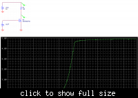
First, a mosfet is a much better choice than the op-amp here because it is much simpler, involves fewer components and calculations, and can handle much higher currents than an op-amp, like this (sorry not sure why I was on the op-amp kick):


Next, as for your relay, let's run the numbers. It's handy that it comes with a board, but a cheap protoboard like the pre-etched ones they sell at RadioShack will offer you a bit more flexibility at a cheaper price (Futurelec is even cheaper although the boards are large, SparkFun has this little guy which is the perfect size for your project although you'll want to check out this nice perfboard soldering tutorial). Secondly, that relay is physically much larger than what you'll actually need for this project. But, I digress. Anyways, the relay:

Let's assume you're using a +5V line from a USB port to power this. By default USB can source 100mA (that's per hub not per port mind you).
Look at the datasheet for that relay: https://www.sparkfun.com/datasheets/Components/T9A_DS.pdf. Look at the coil data table on page 1.

- 5V coil current is 185mA or 200mA (depending on model). This is greater than the 100mA maximum from USB.
- Minimum contact load 1A @ 5VDC, which is significantly larger than your 300uA signal.

So as you can see, this relay will not meet your requirements. This relay is designed to switch higher voltages and currents and is not appropriate for your project.

Let's assume you are using the circuit I just posted (parallel port control) with power from the USB line (5V, 100mA max) and work from there (I am also assuming all your measurements are correct):

First, the relay. Basic electrical requirements are:
- <= 5V coil voltage, < 100mA coil current.
- > 7.7V switching voltage, > 300uA switching current max.
- Minimum switched load < 300 uA.
- normally-open contact (if SPST, but SPDT is fine too).

Head to Mouser's relay section (or Digikey if you prefer) and do a search for these requirements. Sometimes it is also easier to search mfr sites directly e.g. Omron has a nice parameterized search for relays that includes more parameters than mouser. Anyways I found these:

- https://www.mouser.com/ProductDetai...=JK6Bpmia/mt8qYhd9YNgoHf5e0I1m4I06RzPVdcpAAQ=
- https://www.mouser.com/ProductDetai...T-US-DC5/?qs=lK7M36XCk6KssDG60issud7i8qmOKDUC

I mention the first one because it's super cheap and would be perfect except the datasheet states it has a minimum 10mA contact load (the minimum exists to guarantee that your signal will overcome normal corrosion and wear-and-tear of the switch, among other things). So unless your switch current was actually something larger, this one isn't guaranteed to work. Also the first one's pin spacing doesn't match a standard breadboard.

So, let's check the datasheet for that second one: https://components.omron.com/compon...68E53B182485257201007DD6A0/$file/G6E_0911.pdf

- Maximum load: 2A @ 30VDC, which exceeds your 300uA @ 7.7VDC requirement.
- Minimum load: 10uA @ 10mV, which is much lower than your signal, so no problem.
- Nominal coil voltage and current: 40mA @ 5V, which USB power can easily handle.
- Pick-up voltage 70%, which means it will turn on above 5*0.7 = 3.5V (and this should answer your USB 4.5V relay question).
- Drop-out voltage 10%, which means it will turn off below 5*0.1 = 0.5V.
- Max voltage 190% (at room temperature), which means you need 9.5V to blow it up.
- Coil resistance 120 ohm (just make note for later).
- Max close time 5ms (also make note; this means you need to send your trigger signal for at least 5ms to guarantee that you close it).
- Also make note of pinout on page 76 of datasheet (standard coil type).

So it looks like this is your relay (Omron G6E-134P-ST-US-DC5). I can't guarantee it's the cheapest but I can guarantee it's not the most expensive. :lol: Also it will fit nicely on that 1" perfboard from sparkfun I mentioned earlier.

Great! Next step is to pick a MOSFET. You want an n-channel MOSFET. MOSFETs are a bit fuzzier with requirements. Your requirements are pretty easy:

- Minimum gate-source breakdown voltage: >= 10V (that'll let you run the gate off your 4.2V line + lots of padding).
- Minimum drain-source breakdown voltage: >= 18V (that'll let you run power to the +12V line if you want + lots of padding).
- Maximum drain current: >= 80mA (your relay coil is 40mA nominal, + some padding)
- Threshold voltage somewhere in the middle of your 0-4.2V signal e.g. 1-3V.

There are other considerations too so I'll just cut to the chase and say a common Fairchild 2N7000 mosfet will get the job done fine (and they're super cheap):

- https://www.mouser.com/ProductDetai...mdCx%2bAA2NB///eDBYfiAxm8hO%2bvIx3eNCzWH3m2A=

Next, resistor R1. You actually don't want this resistor if you're using VCC=5V. But I want to mention it because you'll have to include it if you use higher VCC to drop the voltage down to the relay coils nominal voltage. Recall the coil resistance is 120Ω and nominal voltage is 5V. V/R=I so 5V/120Ω≈42mA nominal current. Now let's say you have VCC=12V. You want the voltage drop across R1 to be 12-5=7 volts (to limit relay voltage drop to 5, also mosfet on resistance is small enough that we'll pretend it's 0 to simplify things, this doesn't need to be super precise). R=V/I so 7 volts / 42 mA = 166Ω so if you use a 12V source R1≈166Ω (166 is not a common resistor value, but 160 is and is fine) will be necessary to protect the relay.

In general you can simplify the above math to R1 = (VCC - 5) / 5 * 120.

That's about it for components. As you can see it's a very easy circuit to build! A couple of notes about using the components:

- You'll notice the relay coil has +/- polarity markings on the coil. Not all relays do but this one does. This is because the relay has some circuitry inside it to suppress inductive kickback when the coil is deenergized, which could otherwise damage your components e.g. the mosfet. Many small consumer relays have this but if you ever find one that doesn't you'd want to put a reverse biased diode across the coil to absorb the voltage spike.
- The mosfet orientation is also important because of the built-in body diode; for n-channel mosfets be sure to connect drain to a higher potential than the source (so here source to ground and drain to relay).
- If it is more convenient for your design you can put R1 (if you use it), the mosfet and the relay all on the same pcb over by the garage door switch, and run VCC, ground, and parallel port data out through your cat5 cable. Or put R1 on the computer side. Or whatever. As with programming, modularity is a general design consideration although for this project it is not really important.

Hope that helps! I am not really an EE, I'm also a programmer by trade, so if anything is confusing above it's probably my fault :lol:!

- - - Updated - - -

This will give a clear picture of the mosfet switch, X-axis is mosfet Vgs (voltage from the data line of your parallel port) Y axis is voltage across relay. You're switching between X=0 and X=4.2 (over whatever the rise and fall time of your parallel port data line is). Note current beings to pass at Vgs(th)=2.1V which you can find on the data sheet, and the curve flattens out corresponding to the Vds≈5 saturation point which you can see in figure 1 of the datasheet.

 
Last edited:

Status
Not open for further replies.

Part and Inventory Search

Welcome to EDABoard.com

Sponsor

Back
Top