Javad1991
Newbie level 4

Dear friends,
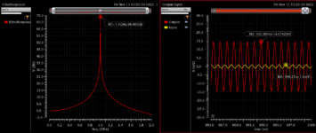
I have designed a bandpass filter (BPF) using an ideal OpAmp and positive feedback (one can consider it a black box). Based on the AC simulation, the BPF is working correctly and filtering other frequencies around 1GHz and passing the 1GHz signal with 68.9dB amplification.
The problem is, when I do a transient simulation with an input of 1mV at 1GHz, the output is only amplified to 15mV, which means the amplification is near 23dB which is far from the 68.9dB shown in the AC simulation.
Can anyone explain this difference, please?
AC and Transient simulation result:

BPF circuit and ideal OpAmp:


I have designed a bandpass filter (BPF) using an ideal OpAmp and positive feedback (one can consider it a black box). Based on the AC simulation, the BPF is working correctly and filtering other frequencies around 1GHz and passing the 1GHz signal with 68.9dB amplification.
The problem is, when I do a transient simulation with an input of 1mV at 1GHz, the output is only amplified to 15mV, which means the amplification is near 23dB which is far from the 68.9dB shown in the AC simulation.
Can anyone explain this difference, please?
AC and Transient simulation result:
BPF circuit and ideal OpAmp:


